Zeroing on Performance
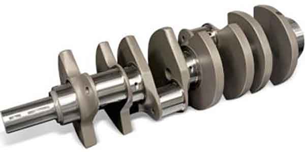
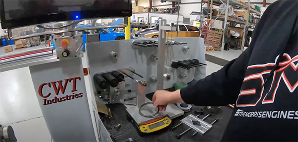
When it comes to balancing a rotating assembly, engine builders have varying takes on what is acceptable and not in terms of reaching a zero balance – that is within 1 gram plus or minus. We recently got the run down on crankshaft balancing from Steve Morris of Steve Morris Engines in Muskegon, MI. He gave us a master class that covered all the steps of how a crankshaft is balanced, why it’s balanced and what you’re actually accomplishing when balancing a crankshaft for a performance engine.
Balancing a crankshaft, in theory, may sound simple. However, there’s a decent amount involved in getting the balance set right, so sometimes it can be a quick process and sometimes it’s not. For those same reasons, crankshaft balancing can sometimes be expensive and sometimes less so, depending on the job.

To begin a balance job, you cannot simply throw your crankshaft on the balancer and spin it without have some form of simulation of what the pistons, rods and everything weighs.
“You have to figure out your bobweights,” Morris says. “The bobweight consists of what is connected to the crankshaft – what is spinning around (on the crank journal) and what is going up and down in the cylinder (rods and pistons). Anything rotating around is called rotating weight, and anything going up and down is called reciprocating weight. You’ll need to weigh these components, but note that you’ll only need to weigh one rod, one piston, two bearings, one set of rings, etc., rather than all of your components. The machine does that math for you.”
Starting with the big end of your connecting rod, you’ll use your scale and a special fixture to suspend the other end to get that weight. Note – make sure your scale is zeroed out before you weigh these components. On the fixture, the rod needs to be parallel, and the small end of the rod suspended.
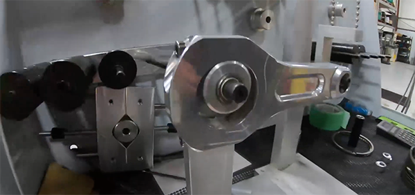
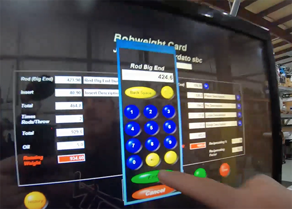
In Steve’s example, his connecting rod weight was 424.6 grams. On your balancer’s input screen, you’ll go to your bobweight numbers to enter in this weight in the appropriate spot on the rotating weight side.
The next thing your balancer will want to know is your bearing insert weight. Steve’s bearing’s – the upper and lower crankshaft bearings – weighed 40.9 grams. Next, you’ll need to enter how many rods per throw are on your crankshaft. Obviously, on a V8, we’re going to have two connecting rods per throw. On a 4-cylinder you’d only have one rod per throw. Something like a straight six will have a different rod throw configuration. Steve’s example follows a standard V8 engine design.
“At this point in the balancing process, you’ve got your connecting rod big end weight, your bearing weight and the number of rods per throw,” Morris says. “The machine will also want to know your oil weight, because yes, there is oil weight involved. Typically, you’re between 3-5 grams, and I typically use 5 grams for that number.”
Those numbers combined give you your rotating weight. Now, you’ll move on to figure out your reciprocating weight. The first item up is the connecting rod’s small end or pin end. Again, zero out your scale and reverse what you did when measuring your rod’s big end. Make sure your connecting rod is level, square and parallel to the scale so you don’t get any bogus readings.
Steve’s small end of the rod weighed in at 177.5 grams. You’ll want to enter this into the balancer’s reciprocating weight entry point. And, you can check that you weighed both rod ends correctly by weighing the total weight of the rod, which in Steve’s case came to 602.3 grams. His big and small-end weights of 424.6 plus 177.5 came to 602.1, which demonstrates he was weighing the rod correctly.
“If you don’t have your rod angle parallel when measuring each end on the scale, it can skew those numbers, so measuring the entire rod is a good idea to check you did it correctly,” he says. “It should weigh what both halves weigh together.”
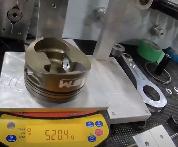
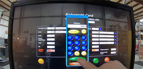
Next, you’ll need the piston weight, which you’ll want to weigh by itself – no rings or wrist pins. In Steve’s example, his piston weight came to 520.4 grams. This weight is entered into the reciprocating weight data. Next, you’ll weigh the pin, which for Steve came to 184.2 grams. And, his particular piston has pin buttons, which hold the pin in from going anywhere and provides support for the oil ring. Those get weighed as well.
“I like pin buttons better than a support rail, but they do add a little bit of weight,” he says. “When we use the pin button, that means we don’t use any kind of spiral lock or clip. The two commonly seen pin supports are a spiral lock with an oil support rail or a pin button. Those are two methods of holding that piston pin from moving back and forth.”
Next, you’ll weigh your piston rings, which in Steve’s case came to 51 grams. All those weights factor into your reciprocating weight, which came to 950.7 grams for Steve. His total reciprocating weight, when you factor in the other rod and piston per throw, came to 1,901.4 grams.
“With the way a crankshaft operates, rods and pistons are opposed from one another,” Morris says. “One is going up in the cylinder as the other is going down. For that reason, you use the original total reciprocating weight you got, which again was 950.7 grams.”
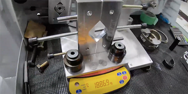
Adding that reciprocating weight (950.7) to the rotating weight (936), gave Steve a total of 1,886.7 grams to use for his bobweight. That’s what’s getting simulated.
“If we change our balance factor from 50% to 51%, which is an overbalance, or 49%, which is an under balance, it changes how heavy the bobweight will be,” Morris says. “At 49%, the bobweight would be 1867.7 grams and at 51% it would be 1905.7 grams. Performance engines will run anywhere from 48%-52% very easily and you’ll never know it.
“There is some math involved, but for racing classes such as Comp Eliminator, Pro Stock and NASCAR Cup series, they’ll underbalance or overbalance, because in an underbalance situation, they tend to accelerate better. In an overbalance situation, they tend to maintain high rpm better. You’re actually not balancing it “correctly” because 50% is the generally accepted ASE method. As racers, we can change and manipulate those bobweights to achieve better acceleration or better high rpm performance.”
In general, 50% is what Morris says he’ll use for everything his shop does, from big rpm to big horsepower, and it works great with no problems. Now that you have your bobweight number, you’ll want to add that weight to your actual bobweight. You can do this in halves or do the whole thing at once. Steve says he prefers doing the whole thing at one time.
Start by zeroing your scale and weighing the bobweight itself, and from there you add weights until you get your desired number. As you add weight, be sure that you’re doing it equally for each side of your bobweight. If you happen to be off by one or two tenths of a gram, it’s not a huge deal.
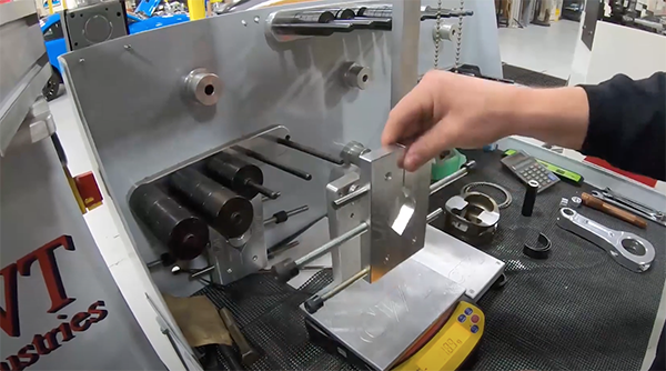
“We’re not going to worry about that because something as light as a single post-it note weighs nearly a gram, so being off a tenth or two is insignificant,” he says. “Once you have your bobweight together, you’ll need to locate it on the crankshaft. What we’re trying to do is get the number one rod throw straight up and down. Use a level to ensure the bobweight is on the crank properly. It’s a little bit more art than science here.
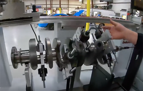
“Each bobweight goes on the crankshaft 90-degrees from each other. Once you have your bobweights placed on the crank, the machine needs to know how far away the bearing is from the other bearing and what the tolerance is. You’ll also want to make sure your balancing in a plane versus a force, because your bobweights are on two different sides.”
Steve suggests balancing at 500 rpm, which is a typical, standard balancing rpm. You can balance at other rpms, but that doesn’t seem to have any bearing. As long as the machine is operating correctly, it should pick up the balance as much as it does at 700 rpm or 1,000 rpm.
“When you see how fast this thing is turning, you’ll see that 500 rpm is a lot, so imagine what’s going on when it’s at 1,000 rpm – not even idle speed,” he says. “Imagine how fast stuff is moving at 10,000 rpm!”
Once the balancer begins spinning the crankshaft, each column of the balancer, which holds the crankshaft in place, has sensors on it to pick up vibrations and movement outside the range you’ve set. The balancer also tells you what position the balance is off at – front or rear on the crank. All positions are either straight up or straight down. That’s where the calculations are factored.
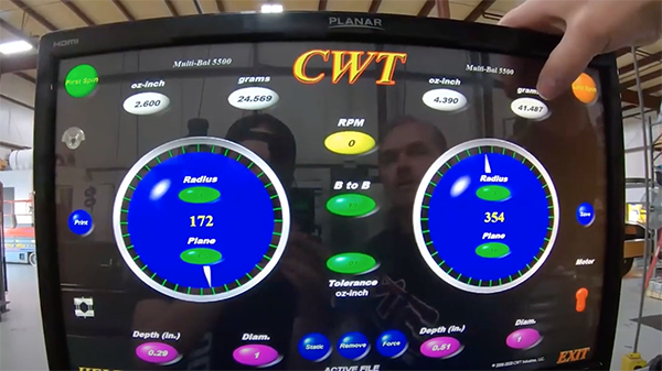
When Steve did his initial balance, the crankshaft, which he got used, was out of balance by 41 grams in the front and 24.5 grams in the rear.
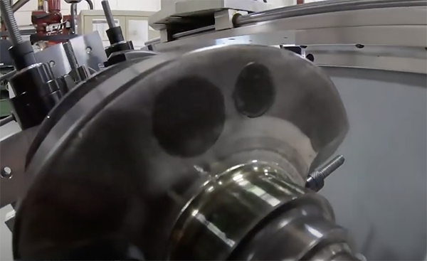
“It’s asking us to add weight,” he says. “If it was asking us to remove weight, we’d use the drill and machine a whole in the counterweight to sneak up on the right balance, moving back and forth between the front and rear counterweights.
“Your other option is to put the crankshaft up in a lathe and balance the counterweight by machining the whole counterweight. Either route you go, you have three planes to choose from in terms of the counterweights to correct. The outer-most counterweight does the most to change the balance and the inner-most counterweight does the least.”
One thing to keep in mind as you do your balance job is that very few things today are externally balanced anymore. All good race engine stuff is internally balanced, so you don’t have to have the crankshaft balancer or the flywheel or flex plate on the crank.
“Those things are neutral balanced,” Morris says. “You can if you want to, but you don’t have to. You also never remove or add weight to the balancer or the flex plate. You only do it on the crankshaft because you want to be able to change the balancer and change the flex plate without having to go in and rebalance everything. That’s why you always do all your balancing within the crankshaft only.
“If we have to add weight, we don’t simply add on metal or weld pieces on – that’s a lower-end way of doing things. What we always do is we simulate what weight needs to be added to the crank using a bolt at first.”
When adding weight to the crankshaft, you use what is called mallory metal, which is quite a bit heavier than the steel of the counterweights. When adding mallory, you should always press it into the side of the crankshaft counterweight rather than the top.
“Pressing it into the side makes it impossible for any weight to come out as the crankshaft is rotating around,” Morris says. “If someone were to weld mallory into a hole on the top of the counterweight, a lot times what can happen is it can fly off the crank and shoot through your oil pan, causing oil to drain onto the track and likely sending you into the wall. That’s why if you need to add weight, we always add mallory metal into the side. We even add a little bit of weld to ensure that it will never slide back and forth.”
In Steve’s example, he added a bolt to the rear of the crank that weighed 40 grams and a bolt to the front that weighed 24 grams, both positioned at 12 o’clock. That’s what the balancer was asking for.
“The machine is giving us a reference number,” he says. “I have never had the machine tell me to put 25 grams right here and I put 25 grams right there and it was exactly right. It never does that, so always sneak up on the correct balance. You want to measure twice and cut once.”

After Steve added his simulated weight and re-spun the crank, the balance was still out by 8 grams in the rear and 6 grams in the front.
“I know now that we’re going to add a little bit more material there,” he says. “Once you have your final weight simulated, then you’ll drill your holes and press in the correct mallory metal and ensure the balance is where you want it.
“One thing to keep in mind – an overbalance or underbalance can be off by 20 grams. Do you really think 6-8 grams really matters? I’m here to tell you it doesn’t. When the crank is spinning inside the crankcase and oil is coming through and getting shed off and there’s windage, everything changes. This is the pragmatic way of doing things. This is not just theory of what’s supposed to be done. This stuff works because we do it every day and I prove it out all the time.”
Next time you’re looking to get a balance job done or doing one yourself, consider that a simple balance job could take 1-2 hours, and a big balance job could take several hours to get right. Don’t take any shortcuts and you’ll be happy with your engine’s performance. EB