There have been several articles done on the subject of valve seats in just about every publication where that content would be relevant. However, in this ever-changing industry, I decided that valve seats would be a good subject to revisit.
Going back to the beginning of our industry, the valve seat was simply a machined or ground surface for a poppet valve to seal in the combustion process. Over time, as uses and applications for the internal combustion engine evolved, engine speeds, power levels, internal pressures, and heat levels increased greatly. Naturally, materials and designs became more specific to the point where today, every part is its own engineering challenge to the manufacturer, as well as the re-builder.
Whether you’re a production builder, small job shop or specialty shop, knowing what to use in the correct application is one of the most valuable tools in your arsenal. As it related to valve seats, it is important to know a bit about the different materials used and when and where it is appropriate to use them.
Engine Builder has covered the topic of valve seats in the past and Larry Carley’s article, titled Understanding Today’s Valve Seats, is worth the read as he covers a wide range of manufacturing processes and applications. However, trying not to duplicate Larry’s good work, I would like to simply convey my personal experience and add to the collection of information this awesome publication provides.
In the early times of the iron internal combustion engine, a valve seat was not even a separate component. As I said before it was simply a machined detail in the combustion chamber for the valve to rest and seal against. As demand on this detail increased, we started to see seats that were pressed into the head or block (obviously in aluminum heads) and made from better material. As vehicle production costs became a factor, most manufacturers continued to machine the seat into the iron casting, but used a flame hardening or induction hardening of the seat area to provide a wear resistant seat. It’s also worth noting that naturally, valves evolved along with seats, creating an important relationship between the two.
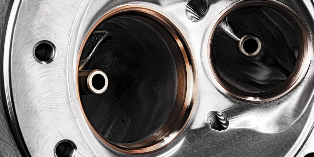
Today, a valve seat must seal the combustion process, dissipate heat from the head of the valve and provide an efficient path for the air, or in most cases, air/fuel mixture, to move from the intake port into the chamber and back out the exhaust side under tremendous heat and pressures, all while keeping its shape to perform over a long life expectancy. The intake seat has an easy life compared to the exhaust seat in that it is air-cooled and has much more seat contact area in which to sink heat. An exception to this is under extreme pressures such as detonation where there is much more square area of valve exposed causing damage or wear to the seat and valve. Also, in dirty environments such as dirt track racing, the intake seat can suffer from accelerated wear due to abrasion.
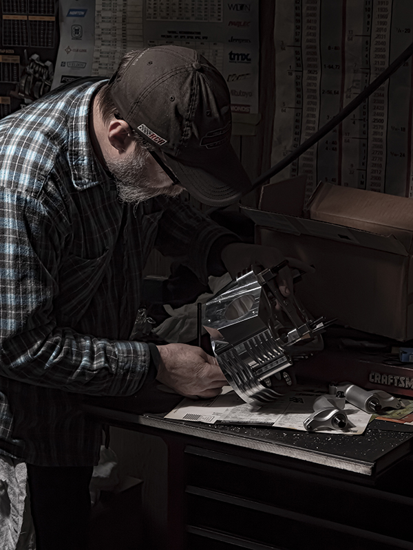
Servicing or replacing seats is a process that I’m sure many of you are familiar with. Having a good solid seat and guide machine is paramount. There are many machines available today, both new and used, but knowing how to get good work from your particular setup is a high priority. When replacing seats, it is mandatory to know exactly where your cutters are “sighted in,” so you can depend on them to give you a precisely sized seat bore. I will discuss my preferred press fits when we get to material selection.
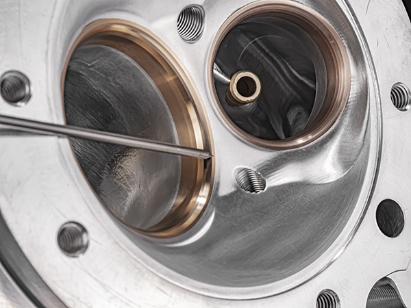
Seats must be installed straight, into a clean, properly sized bore. In high interference installations, such as in aluminum heads, I like to warm the head to around 160 degrees and freeze the seat and driver to aid in a smooth fitting action. I also make sure to have a slight radius on the O.D. of the seat, so it doesn’t shave material going into the bore. Carefully touching the bottom edge in a turning motion on a running crank polishing belt works really well.
In the area of the seat where the valve rests, as well as the areas above and below the contact point, angles can be ground or machined. I’ve noticed over the years that old school engine guys who had a thorough understanding of how to obtain a good angle package with stones were a bit better at understanding the ins and outs of seat angles and how to best use them. For any young engine builders wanting to get into this trade, I recommend learning to use the old, dusty seat grinder for a while to get started. That and some ink can teach you volumes on valve/seat relationships.
While we are touching on grinding, I will say that before we moved to V-Twin high performance only, we did some medium and heavy-duty diesel heads, and although we cut many seats in our machine, we always touched the seat with a stone to be sure the hard seat material was where we wanted it. Many times, we were told that our head “sounded better” on a running engine than other rebuilders’ reconditioned heads. That being said, it is nearly impossible to obtain the consistency and accuracy available with today’s equipment using yesterday’s machines. The repeatability and speed of operation of a good modern machine, whether a formed blade or exotic single point live head, is great to have and required for most of today’s work, but I wouldn’t get rid of that old seat grinder. You just never know when it might help you out.
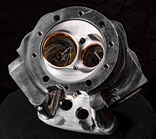
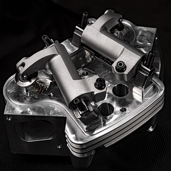
Since moving to mostly V-Twin motorcycle machining, seat replacement has become more common in our shop, particularly in vintage heads. Iron heads like early Sportster or Knuckleheads usually get modern, powdered-metal seats installed with .005˝ press fit. That same material installed in a later aluminum head requires .007˝ interference fit to keep from moving when temps rise.
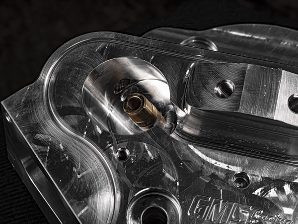
In racing heads, we use copper/bronze/nickel which we have found to take less interference fit as mentioned below. One of the more interesting applications is the Harley Panhead. They were made with a soft brass seat that is cast into the head. When machining for replacement, I treat them like an iron head with cast-in iron seats. With the bores machined, there will almost always be some brass left in the head. To try to get it all would mean making the bore too large. I always replace them with the latest copper/bronze/nickel seat so as not to crack the old aluminum in those particular heads with the high press fit needed with powdered metal. The result is a good repair that lasts a very long time.
When researching materials, I reached out to Martin Wells, a well-known company that has been revived by the employees who most recently worked under that brand. Something they have available is “Well-tite,” a proven formula with a 50+ year history in natural gas, propane and diesel applications. In those areas, resistance to extreme heat and corrosion is needed for both OEMs and re-builders. This alloy is in the nickel-chrome family and has a hardness of 32-38 on the HRC scale.
An even tougher alloy is Martin Wells’ “X-Tite,” which is also a nickel-chromium with cobalt and tungsten added to make this material extremely tough. This alloy is 45-50 on the HRC scale.
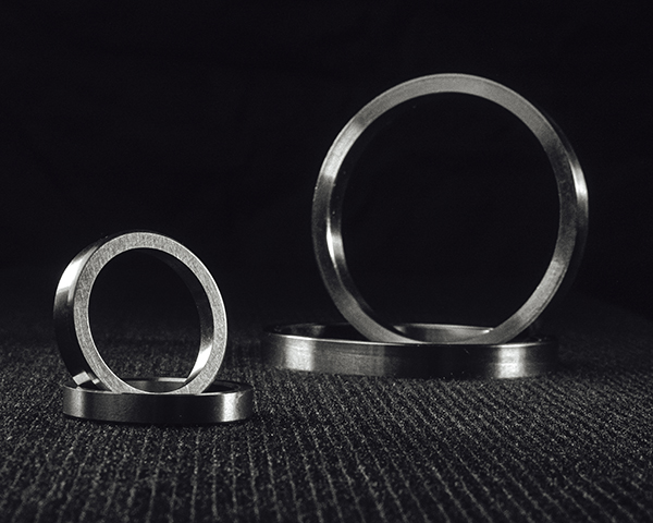
I recently asked Martin-Wells if they would produce a copper/bronze/nickel seat for use in high performance applications where titanium valves are in use. They came back to me with a centrifugally cast seat that meets our needs. This type of seat has excellent heat sinking from valve to seat to head and also has a thermal expansion rate that more closely follows aluminum, thus requiring less interference fit – around .005˝. There are several similar formulas available, but having someone work with us to produce a seat for our needs was too good to pass up.
Aside from your seat material, another thing to consider is your valve seat angles. In competition engines, valve seat angles have gone from the standard 45 degrees to 55 and sometimes 60 degrees or more. High seat pressure, fast ramp/high lift cam profiles and high rpms create tremendous seating pressure with these steep seat angles. In this case, the copper/nickel-based seats are a must. Today’s chromium-nitride coated titanium valves along with the copper/nickel seat provide great performance and good life for intended use, even in nitrous and boosted applications.
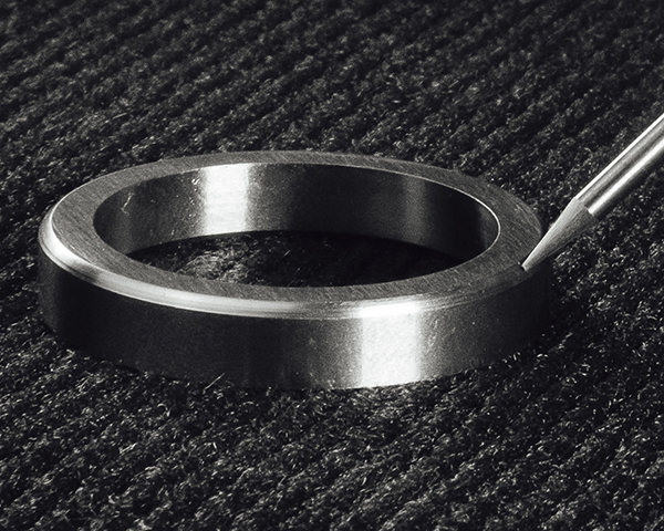
I’ve also seen in racing heads, especially ones that have been out there for a long while, seats that have had their I.D.s over-sized to the extreme, which causes a very thin radial cross section. This is usually from oversized valves being installed either for more airflow or to repair a worn head. A situation like this will not turn out well because the seat will deform and leak, lose its heat transfer capability, and in severe cases, fall out or breakup. Look for this when servicing high-performance heads and replace the seat. I would also stay away from shallow seat installations as well. For extreme applications, I like to see a minimum of 7/16˝ seat depth and 3/16˝ radial wall thickness at the base.
Remember, the valve seat is part of a complex system that must work in conjunction with the other parts of the system under harsh conditions and work in that environment for its intended life span. Like every other component in the engine, the part must be correct for the application and properly installed and maintained. As always, good shop practices will never fail you. EB