Thanks to the ever-increasing horsepower, torque and loads today’s engines are put under, there are going to be times where critical components such as blocks and cylinder heads will crack due to the stress. But don’t fret! There are a number of ways to check for those cracks and repair them.
We’ve talked a lot about crack detection over the years – everything from wet and dry magnetic particle inspection to dye penetrant crack detection to vacuum testing. Another avenue is pressure testing. This method is often used along with one of those listed above as a final check that all of the cracks or pinholes have been repaired. There are two ways to perform pressure testing – wet or dry. The good news is the procedures are essentially the same regardless of which method you choose.
First of all, the head being tested needs to be completely clean. You will attach a special block-off plate to the head to seal off the water passages, then pump pressurized air into the head through an air line inserted into a water port. Some sources will tell you to use about 60 psi, but in my experience, 20-25 psi is adequate. Some heads have core plugs pressed into them and these will blow out at 60 psi. It’s not only an inconvenience, it’s a safety hazard.
Here’s where the methods differ. With the wet method, you’ll lower the head into a water tank until it’s completely submerged. If you have holes or cracks, the escaping air bubbles will show you where. The dry method is similar. Instead of taking the head to the water, you’re bringing the water to the head. Once the head is pressurized, you’ll spray it with a soapy solution (bubble fluid or a little dish soap in water). If there are cracks or holes, the solution will bubble up and you’ll know where you need to repair.
Pressure testing is one of the easiest of the crack detection methods available. But a major drawback is that pressure testing can’t identify all cracks. Surface cracks that don’t connect to a water passage won’t show any leakage so you could miss those if you just use pressure testing.
For that reason, chemical crack detection can come in handy. As you all know, there are no magnets for aluminum. I’m sure someday we will develop it, but for now chemical crack detection is one avenue you can take to find cracks in your aluminum engine parts.
There are a couple of ways Goodson can help engine builders with chemical crack detection. First is our AC kit, which has been in our product line for years. It uses a proven chemical process and it has three parts to get it done. AC-1 is a cleaner and is what you use to clean the work piece. AC-2 is a penetrant and gets sprayed on the work piece. Lastly, AC-3 is the developer itself. Just like developing film, when we spray this on after the cleaner and the penetrant, it will develop where the crack or cracks are.
That AC-3 spray will actually change the color of the silver aluminum into a reddish/orange color, which can be seen by the eye quite quickly. This is an alternative method to checking surface cracks on aluminum.
Of course, we’ve all got pressure testers in our shops, and I’m not trying to take away from the pressure testers. You’ve got to have a pressure tester because it’ll check all the water passages and oil galleys, where with the chemical check you can only check surfaces that you can actually spray to. And, we’re subjected to the ability of our eyeballs to see that chemical reaction and know where those cracks are and to take either the appropriate measures to repair that work piece or change it out for a core with better integrity.
To help in the visual realization of the chemical process against these work pieces, Goodson also decided to make a GLO kit, which like the AC kit, has a cleaner, a penetrant and a developer spray. However, the beauty of the GLO material is it reacts to UV light. When you shine a UV light over your components, any crack or cracks will literally pop off of the aluminum surface for easy detection. Goodson sells a Maxion DFL 364 UV light to accompany the GLO kit chemicals.
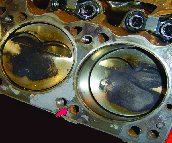
As mentioned, we’ve talked about how to find cracks in cylinder heads and blocks, but now it’s time to discuss repairing the cracks you’ve found. Let’s start by saying that not every crack you find needs to be repaired. If the crack isn’t located in an oil passage, bolt hole or other seal surface you don’t need to fix it completely. You do, however, need to stop the crack from growing. If you don’t, odds are you’ll be fixing it in the future.
To stop the crack from growing you need to do what’s called “stop drilling.” This means you drill a tiny hole – about 1/8˝ diameter – just past the ends of the crack. This hole will relieve the stresses placed on the metal and keep the crack from expanding.
As with most operations in the machine shop, there are multiple methods you can use. Some methods work better on certain materials (cast iron vs. aluminum, for example) and some are just pure personal preference. The most common methods for crack repair used in automotive shops are tapping and plugging, welding, sealants, and inserting sleeves. For now, we’re just going to cover crack repair plugs.
The most common system available for tapping and plugging cracks is Irontite. As the name implies, this method of crack repair requires taps and plugs. You will also need correctly sized drills and tapered reamers.
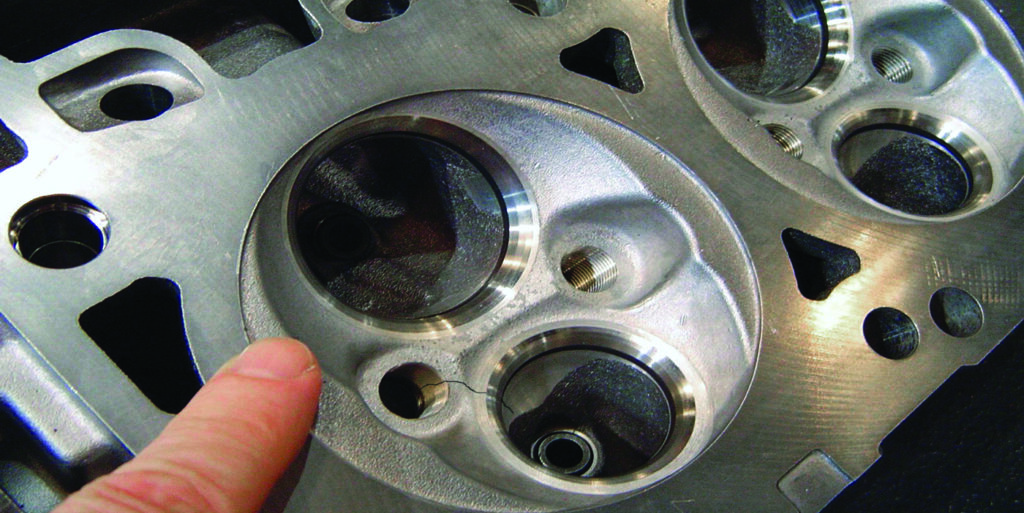
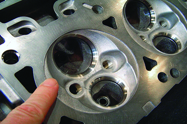
The first type of application we’ll talk about is installing tapered plugs to repair a crack in the area of a casting that is subject to high pressure and/or temperatures. A perfect example of this is a crack in the valve seat area of the head. To repair this type of crack you’ll install the plugs at an angle to the casting surface, not perpendicular. You will also be overlapping the plugs.
1. Drill a plug hole at least 1/8˝ past the visible ends of the crack. This is to stop the crack from growing as you put pressure on the casting by installing plugs. Be sure to use compressed air to clean out the holes, every step of the way.
2. After drilling, use a tapered reamer in the hole to make tapping easier and reduce tap breakage. This is particularly important where the material you’re drilling through is thick.
3. Next tap the hole at one end of the crack. Be careful not to tap too deeply. You may run into another wall within the casting or the plug might seat too deeply before it is tight. One rule of thumb is to count the number of threads in the hole and tap so that the plug goes in the same number turns. For example, you have six threads, so you turn the plug six times.
4. Dip the end of the threaded plug with sealer such as Ceramic Motor Seal or Fluid Weld and tighten it into the tapped hole.
5. Saw off the excess plug material. For best results, be sure to cut at least half-way through the plug before snapping off the remaining material. This should keep the plugs from snapping off below the surface.
6. Peen the surface of the plug and the surrounding area.
7. Be sure to locate the next plug so that it overlaps the one you just installed. You will continue in this fashion until the entire crack has been repaired.
The peening process is extremely important. It helps close the threads at the surface of the casting. When peening, always peen away from the center of the plug. In the peening process, the position control of the air hammer is most important. It provides the necessary control over the direction of the ends of the peening tools.
A similar, but slightly different application is used when repairing cracks in easily accessible areas of the casting that aren’t subject to high pressure or temperature and the metal is relatively thin.
After the crack is outlined, drill and tap holes along the line of the crack about 1/4˝ to 1/2˝ apart. Where the material is less than 1/4˝ thick, it is not necessary to ream before tapping.
- Capture the crack at each end.
2. Torque the plugs in concurrently so that none of them will be loosened as other plugs are torqued in. Be sure to dip each of the plugs into sealer.
3. Cut the plugs off about 1/16˝ above the surface and peen them. Always peen from the center of the plug toward the thread in the plug.
4. Peen the crack itself, peening inwardly toward the center of the crack.
You can also drill and tap the holes in a lacing fashion on opposite sides of the crack. You’ll torque the plugs in at the same time and then cut them off. Peen the plugs and the crack in the same manner as above. This process, in addition to closing the crack with additional metal and with peening the crack, develops a resistant elasticity in the metal, which helps keep the crack closed.
Some final tips, tricks and cautions are to be sure to use the proper amount of downward pressure with the tapered tap. You’ll also want to use a good tapping fluid. Use the same material for the plugs as the head is made of. For example, if you’re repairing a cast iron head, you’ll use iron plugs. You’ll also need to be sure that you have actually repaired the entire crack by pressure or vacuum testing.
These are just a few methods of crack detection and repair, but they could save you and your engine from further damage. EB


