Engine cooling doesn’t only happen at at the radiator. The valves (particularly the exhaust valves) take a lot of heat from the combustion chamber and the valve seats have the responsibility of helping to cool them off. The seats draw heat away from the valves and conduct it into the cylinder head, providing most of the cooling that the valves receive.
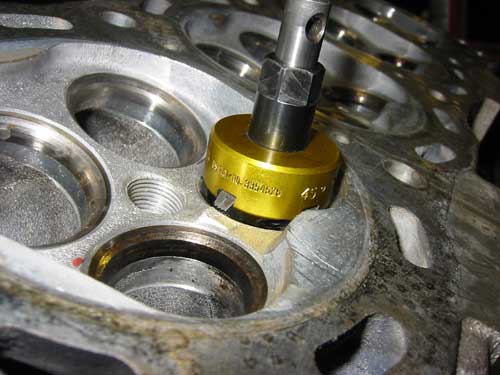 Anything that interferes with the seat’s ability to cool the valves (such as a loose fit or deposits between the seat and its counterbore) can lead to premature valve failure and expensive comebacks, so a cylinder head job often requires valve guide and seat work to restore it for service or to improve performance. In order for a valve to seat correctly, for efficiency and power, engine builders must replace or bring back to spec all valve seats and guides.
When considering the steps necessary to repair or replace valve seats, be aware that with two types of cylinder heads you have three options: aluminum with removable valve seats or cast iron, with removable or integral hardened seats. If the cast iron head has integral seats it will need to be machined to replace the seat. If the head is aluminum, the seat counterbore may have to be machined to accept an oversize seat if the bore is loose, deformed or damaged. Either way, you’ll need to figure the amount of interference that is required for the new seat before cutting the head on a seat-and-guide machine.
Valve seat replacement is required if the cylinder head was warped and needed to be straightened before resurfacing. Similarly, if an aluminum head was cleaned by heating, the seats will need to be replaced.
If the valve’s mating surface has receded below factory specifications or if machining the head would cause the seat to fall below factory specs, it must be replaced.
Replace the integral seats in a cast iron head if the head has been ground before, because the hardened depth of the head used in the seat area will be too shallow to allow a second grinding.
If the valve seat insert shows evidence of being loose or doesn’t have adequate interference; if there is evidence of corrosion on the cylinder head around the outside diameter of the valve seat; or if there is evidence that the seat has any cracking, burning, pitting or fissures, the seats must be replaced.
The seat alloy and hardness must also be matched to the type of fuel used and the engine application and compatible with the type of valves that are installed in the engine. Again, there are often differences of opinion regarding the selection and use of various seat materials.
Nonintegral valve seats can fail for a number of reasons. Most of the seats that end up being replaced are either cracked or too worn to be reground or remachined. Seats can crack from thermal stress (engine overheating usually), thermal shock (a sudden and rapid change in operating temperature) or mechanical stress (detonation, excessive valve lash that results in severe pounding, etc.).
A small amount of valve recession results from normal high mileage wear, but it can also occur when unleaded gasoline or a “dry” fuel such as propane or natural gas is used in an engine that isn’t equipped with hard seats. Recession takes place when the seats get hot and microscopic welds form between the valve face and seat.
Every time the valve opens, tiny chunks of metal are torn away and blown out the exhaust. Over time, the seat is gradually eaten away and the valve slowly sinks deeper and deeper into the head. Eventually the lash in the valvetrain closes up and prevents the valve from seating. This causes the valve to overheat and burn.
Compression is lost and the engine is diagnosed as having a “bad valve.” The seat also has to be replaced, but in many instances it may not be recognized as the underlying cause of the failure.
As a rule, most experts recommend replacing OEM valve seats with ones that are of a similar material – except in cases where extra durability is required because of a change in fuels (converting to propane or natural gas, for example), or an engine is being built for racing.
There are a number of different valve seat materials from which engine builders can choose. Many of these materials will work in a wide variety of performance applications while others are designed primarily for special applications such as industrial engines that run dry fuels like propane or natural gas. The only consensus is that different valve seat materials can be used successfully in most performance engines.
What kind of materials are we talking about? Everything from nodular/ductile iron alloys and powder metal steel seats to hard aluminum-copper and bronze alloys, and beryllium copper alloys. Many valve seat suppliers have their own proprietary alloys while others use industry standard alloys. But you don’t have to be a metallurgist to appreciate the differences between some of these materials.
A valve seat must do several things. It must support and seal the valve when the valve closes, it must cool the valve, and it must resist wear and recession. Consequently, a performance valve seat material should provide a certain amount of dampening to help cushion the valve when it closes at high rpm. Very hard materials, especially on the intake side, are not the best choice here because intake valves tend to be larger, heavier and close at faster rates than exhaust valves. The wilder the cam profile, the more pounding the valve and seat undergo at high rpm.
Many late model domestic and import engines have seats that are made of powder metal. These types of seats are very hard and durable, so they typically show little wear at high mileages. Consequently, the seats may need little work when the cylinder head is rebuilt.
One difference between cast alloy seats and powder metal seats is the way the seats are manufactured. Cast alloy seats are made by melting and mixing different metals together so they combine chemically. The molten soup is then poured into a mold and cast to shape. The rate of cooling and subsequent heat treatment of the metal determines its microstructure, hardness, strength and other physical properties.
Powder metal seats, by comparison, are made by mixing together various dry metal powders such as iron, tungsten carbide, molybdenum, chromium, vanadium, nickel, manganese, silicon, copper, etc.), pressing the mixed powders into a die, then subjecting the die to high heat and pressure (a process called “sintering”). This causes the powders to bond together and form a solid composite matrix with very uniform and consistent properties.
One of the advantages of powder metal sintering is that materials that are difficult or impossible to mix together in a molten state can be blended together and bonded to create totally unique materials. For example, in powder metal bushings and ball joints, graphite is combined with steel to make the material “self-lubricating.”
Another advantage of the powder metal process is that parts can be manufactured very close to final tolerances, reducing the amount of machining that’s needed to finish the part to size. This lowers production costs and boosts manufacturing productivity.
The main reason why vehicle manufacturers have switched from cast alloy seats to powder metal seat inserts is to extend durability. Most late model engines have to be emissions-certified to 150,000 miles or higher depending on the application and model year. If the valve seats can’t go the distance during durability testing, the vehicle manufacturer can’t certify the engine.
Powder metal seats are very good at handling thermal stress as well as impact stress, and typically show minimal wear after tens of thousands of miles of use. The homogeneous consistency of a powder metal seat also improves heat transfer, which is good for the valves, too. Powder metal seats also tend to experience less micro-welding between the seat and valve even at high combustion temperatures, which helps extend the life of both components.
Exhaust valves run much hotter than intake valves so cooling is more critical on the exhaust side. Heat transfer from the valve to the seat provides cooling during the time when the valve is closed, and by conduction up through the valve stem and into the valve guide and head.
It’s more noticeable in performance engines. Titanium valves do not shed heat as quickly as stainless steel valves, so the tradeoff for switching from steel to titanium to save weight is often hotter running valves. The higher the temperature of the exhaust valve, the greater the risk of the valve causing a preignition or detonation problem.
There is also increased risk of the valve burning. That’s why many suppliers of titanium valves recommend seat materials such as beryllium copper.
For racing applications using either stainless steel or titanium exhaust valves, some suppliers recommend a sintered valve seat insert, which includes a blend of finely dispersed tungsten carbide in a matrix of tempered M22 tool steel and special alloy iron particles. These powder metal seats have a very uniform microstructure, and are highly machinable. Because powder metal seats work harden as they age, they don’t have to be as hard initially to provide good long term durability, and the self-lubricating qualities of the material allows it to handle a wide variety of fuels, including unleaded and leaded gasoline, straight alcohol, nitrous oxide and nitro methane. A shot of nitrous will cause combustion temperatures to soar, but the dose usually doesn’t last long enough to have any detrimental effect on the seats.
The next step up is a high alloy seat material, for applications where high heat resistance is required, such as a propane or natural gas fired stationary engine but also for high performance engines, heavy-duty and extreme duty engines where longevity is a must. Seats are made out of a high speed tungsten carbide tool steel, which gives it ceramic-like characteristics for extreme temperature resistance.
Conversely, because they tend to run much cooler than exhaust valves, low alloy seats work well with intake valves in performance applications, even in such extreme cases as offshore racing boats that run for hours on end.
Equipment Selection
Seats that are cracked, loose, sunken or destroyed in some manner must be replaced with new. Drilling, reaming, replacing valve guides, removing worn, loose or damaged valve seats, cutting new seat counterbores and machining valve seats are all part of the reconditioning process that your shop must be able to handle as efficiently as possible and with precision and accuracy.
There are a few different kinds of seat and guide machines available today to fit most budgets. The first kind of machine is not much more complex than a drill press and is often referred to as such. In these seat and guide machines the tooling sets in a solid column and the table floats to move from guide-to-guide. These are very basic seat and guide machines that have some limitations compared to more advanced machines, however, there are still some small shops and hobbyists that use this style of machine. A small shop may not be able to justify the larger, more expensive machines, and many of these small shops simply don’t have the volume to be concerned about doing hand grinding and lapping.
The second level of seat and guide machines is the floating powerhead system. These machines have become the industry-standard for many engine builders today. This equipment, according to the manufacurers we surveyed, run in the price range of about $18,000-$30,000, depending on the options and manufacturer you choose. On these machines, the cylinder head is stationary underneath a floating powerhead. The powerhead floats above on flat ways that adjust front-to-back and side-to-side.
The powerhead weighs much less than the cylinder heads, so when you center the powerhead, a procedure similar on most models, it floats and centers with the pilot. Once it is centered over the pilot, you let off the foot pedal to lock it in place. This setup gives you a very rigid platform.
Modern cylinder heads often have canted valves so on an older-style machine you have to tilt the fixture to machine canted valve seats and guides. The fixture is relocated and set for each guide. When using a modern seat and guide machine, the powerhead tilts, allowing you to adjust the powerhead for whatever angle you need. Once you’ve set the powerhead angle you can go up and down the line with the same tilt angle for each valve seat. Some machines can accommodate up to 15 degrees of rotating tilt.
Today’s valve seat and guide machines also use three-blade carbide cutters with three-angles or more. These cutters, or form tools, give you a very consistent profile and concentricity because the profile is built into the tooling. Manufacturers vary with the type of tooling each offers, but all are essentially a form tool with built-in angles.
The third style seat and guide machine is the “live pilot” design. Whereas a “dead pilot” design remains stationary in the guide as the tooling rotates, a live pilot spins with the tooling in the guide. You have to be very precise when fitting live pilots into guides otherwise too much play could result in a seat that isn’t completely round. Some live pilot machines have a single blade carbide cutter that can adjust while it spins to create almost an infinite number of profile.
To download a PDF of the complete 2009 Machining & Engine Parts guide, click here.

