The amount of electronic and electrical equipment
in today’s cars has increased exponentially over the past decade
and we can look forward to even more in the near future. The demands
for electrical power are increasing and, consequently, greater
output currents are needed from the alternator. In this article,
we will examine what determines the output current of an alternator
and will look at a high output alternator originated from stock
parts, as well as a “built from scratch” unit.
The basics
In the early 19th century, Michael Faraday
discovered that if you move a conductor within a magnetic field,
a current will be caused to move within the conductor. It is on
this principle that the modern alternator operates. The rotor
coil generates a magnetic field that is intercepted by the stator
core that passes this “changing” magnetic field into
the stator coil, in turn producing an electrical current. The
alternator is a transducer that converts mechanical energy into
magnetic energy, then magnetic energy into electrical energy.
It’s not possible to cover every detail of
alternator design in the confines of one article. However, by
knowing the basics of unit operation and testing methods, one
can understand how to generate more output current from a given
alternator.
In modern electronics most electronic components
have a defined “mathematical model” developed through
a process called finite element analysis. Information is generated
which shows how a bunch of electronic components will behave when
connected together in various ways. Models have been developed
for magnetic devices such as transformers and solenoids. But to
my knowledge, no one has published a program for designing an
alternator.
If such a program were available, you could
key in the basic parameters such as speed range, output voltage
and current, expected temperature rise, expected current at idle
speed, expected stator wave form, maximum speed required, etc.
A click of the mouse button and your computer could then tell
you what stator core size to use, recommend thickness of laminations,
determine how many turns and what stator wire gauge to use, state
the rotor pole geometry and cross-sectional size, recommended
gauge rotor coil wire and how many turns should be employed.
Furthermore, your computer could determine
what size rotor shaft is required plus the bearing size, what
pitch fan to use and the minimum size of the shell required to
house the unit. Unfortunately, until such a program is available,
the design of an alternator is almost as much art as it is science.
By applying basic electrical principles to
alternator design, though, we can learn a lot. And, there are
more than 30 years of operating alternators in the field. As the
old saying in the engineering field goes, you don’t have to reinvent
the wheel to improve upon existing designs.
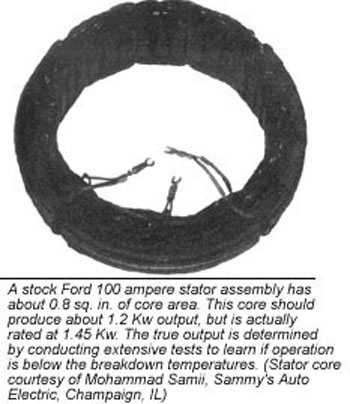
The stator core
If you disassembled an alternator, you would
notice that there are no wires attached to the stator core from
any kind of input energy source. The only energy that can be passed
into the stator core is the magnetic energy from the rotor. A
stator core does not care if its coils are generating 1,000 volts
at one ampere or one volt at 1,000 amperes. The key specification
of a new alternator design is, therefore, “output power.”
And output power is the product of volts times amperes.
If you take off one of the end caps from an
alternator and view the relationship of the rotor pole pieces
to the stator core, you should realize that the magnetic force
of one of the rotor poles is trying to get to one of the adjacent
poles that is mounted on the opposite side of the referenced pole
piece. To get there, the magnetic flux travels outward into the
stator core, goes both left and right, then down to the opposite
pole piece.
The output power of the stator core is then
dependent on how much magnetic energy the core can handle. There
is only a limited number of materials suitable for core construction.
Non-grain oriented soft steel is the most common material. The
amount of magnetic flux this material can handle is almost constant
due to the natural permeability of this type of steel.
The key then is to apply a magnetizing force
to the steel. Using a gauss meter (a device for measuring the
amount of magnetic flux), find the point where further increases
in magnetizing force does not increase the amount of flux density
of the core material. When increases in magnetizing force do not
increase flux density, the core is said to be saturated.
The only way to get more output current from
a core is to increase the size, or more precisely, the cross-sectional
area of the core. For simple closed-loop cores, output power equals
0.5184 times the frequency (in Hz) times the cross-sectional area
(in inches) squared. This equation is only a ballpark approximation
of how much power you can get from a given cross-sectional area.
An alternator stator is a complex device in
that the stator core is composed of segmented sections for each
pole. A six-pole stator (one with six fingers in each rotor pole
piece) can be thought of as six sub-cores where each core only
has one-sixth of the total stator winding. In effect, each core
section is in parallel so that the total cross-sectional area
of the core need be only one-sixth of that computed by the core
size equation.
The stator receives its magnetic energy from
the rotor. As the rotor must rotate, an air gap is required; for
each pole there are two air gaps. An air gap has high reluctance,
therefore, it consumes a great deal of magnetic force, lowering
the magnetic force across the stator core cross-section. With
lower magnetic force across the core, the flux density decreases
requiring a larger core.
Following this line of thought, the core size
is decreased by adding more poles to the alternator, but increased
due to the air gap. The force across the air gap increases by
the square of the distance. For example, if the original air gap
was 5 mils and you reamed out 2.5 mils from the center of the
stator core, the gap distance would double, dropping four times
the magnetic force. The size of the air gap is extremely critical
in alternator performance.
From the core size equation note that the power
output is (within limits) proportional to the frequency, but it
increases by the square of the cross-sectional area. If you have
a 1,000 watt stator that you want to make into a 2,000 watt stator,
you would have to increase the cross sectional area by the square
root of two or 1.414ý. While this is not exact, it will
be close for testing.
The ideal cross-sectional shape of the core
is a square in terms of the stator winding. A square has the smallest
perimeter for the area. Rectangular shapes use a lot more stator
wire for the same cross-sectional area. The exact wire gauge size
to use depends on the efficiency of your alternator. Larger wire
(smaller numeric gauge size) runs cooler, but you may not have
space for the larger size.
Magnet wire manufacturers have charts telling
what gauge wire to use for a certain temperature rise. If your
wire has a high temperature insulation you can sacrifice efficiency
and just let the stator run hotter. The energy consumed by the
wire is called copper loss and is equal to the TRMS (True Root
Mean Square) value of the winding current squared times the winding
resistance.
You have a choice of connecting the three windings
in either a delta or wye circuit. The delta lets you use a smaller
diameter wire, but requires more turns as each coil must develop
the full output voltage. The wye needs a larger diameter wire,
but requires fewer turns as two coils are in series.
You don’t get twice the voltage as the two
windings are 120° out of phase; you will get the square root
of three times a single winding voltage. As a delta configuration
forms a closed loop with the three windings, any imbalance in
the turns ratio or wire length results in a large loop current.
The idea of an alternator is to provide an output current; delta
loop currents take away from the output current and just cause
excess stator winding heat.
Delta coils should be tested for uniformity.
Just place a TRMS-AC ammeter in the delta loop (while not drawing
any output current) and run your test alternator at full speed.
A couple of amperes is okay for loop current as you will never
get a perfectly balanced stator. But more than this requires adjustments
to the coil winding equipment.
The stator core has losses called hysteresis
losses due to the continuous remagnetizing of the core material.
Eddy current losses also exist due to the fact that steel is a
conductor that sees the same changing magnetic field produced
by the rotor. To reduce hysteresis losses the core steel must
be physically soft.
A permanent magnet is hardened steel and is
difficult to demagnetize; soft steel does not retain magnetism.
The laminations should be annealed to soften the material. Annealing
also oxidizes the laminations to provide lamination-to-lamination
resistance. An odd thing about oxidation is that most base conductors
such as copper, silver, steel and aluminum are good conductors
until oxidized. Most metal oxides are good electrical insulators.
Laminations should be treated like fine china.
Steel is hardened by forging, a pounding process; tossing a stator
core into a bin does the same thing. Hardened steel requires more
energy to constantly magnetize it, resulting in more core heat.
Electricity intended for higher output current is used to heat
the core.
To reduce eddy current losses, the core is
laminated to form thin sheets. The reduced cross-sectional area
of each lamination offers a greater resistance to current. Super
thin laminations would seem to be ideal to minimize eddy currents
and such is true in terms of just eddy currents. But the oxide
coating on each side of the lamination is not magnetic, therefore,
non-magnetic regions are formed that somewhat defeat the purpose
of the core.
If the laminations are made too thin, a parameter
called “stacking factor” enters the equation requiring
that more laminations are added to provide the minimum cross-sectional
area resulting in a thicker core. A thicker core requires longer
wires to form the stator coils, increasing the stator resistance
resulting in additional copper losses.
In terms of copper and core losses, the ideal
stator assembly will be designed in such a way that the copper
losses are equal to the core losses. This power loss equality
results in the most efficient stator; and an efficient stator
outputs more current. Use a TRMS ammeter in series with each stator
coil, and multiply this current times each stator coil’s resistance
as measured by an ohmmeter. Adding the three coil powers together
provides the copper loss values.
Measuring core loss is not as simple. Core
loss varies considerably with frequency. Typically, most alternators
will not output more current when the speed approaches 6,000 rpm.
This is due mostly to core losses. At these higher frequencies
the core cannot be remagnetized fast enough and the eddy currents
increase drastically.
Increasing the speed results in a flattened
current curve. The speed where the current flattens out is a good
point to check core losses. Another frequency of interest is the
normal idling speed of the alternator; concern about output current
is important at this speed.
In power transformer design, determination
of core losses is easy as the input, output and copper loss power
can be measured. Simply subtract the sum of output power and copper
loss power from the total input power and you have core loss power
as the difference.
Such is not the case in an alternator as the
input power is mechanical rather than electrical. To measure mechanical
input power a device called a rotary strain gauge transducer is
mounted between the drive source and rotor with some type of tachometer.
The strain gauge transducer provides input torque and the tachometer
provides speed so that input horsepower can be calculated.
An easier way to determine core loss, say at
6,000 rpm, is to divide this speed by 60 RPS and multiply this
result by the number of pole pieces. For six poles this gives
us a stator frequency of 600 Hz. With data provided by your core
lamination supplier, this frequency will provide a certain number
of watts per pound of core loss. Simply weigh your coil-less core
and multiply it by the watts per pound value to learn the total
core value.
With core and copper losses known, you can
adjust each by changing core geometry, lamination thickness, lamination
type and wire gauge size until you find the optimum value. Sound
like work? It is! Even though you may never design a stator, you
should understand what goes into its development and gain an appreciation
for how critical stator parameters are.
Determining the number of poles is the next
item in alternator design. Generally, more poles result in a greater
stator frequency that would cause a stator to output more current
at idle speed. If this is your goal, use more poles. But adding
more poles results in thinner pole sections resulting in finger
fluctuations at high speeds which require a larger rotor-stator
gap.
Core losses also increase with more poles,
limiting the high-speed output of the alternator. When designing
an alternator, the phrase “trade-offs” enter the picture.
When you improve one parameter other parameters suffer. A good
alternator design depends on optimizing each parameter to get
an overall balance in the design. It also takes skill and patience.
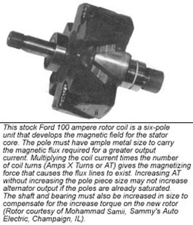
The rotor
There is a choice to be made of either rotating
both the pole pieces and the coil, or just the pole pieces around
a fixed coil. The rotating coil method requires the familiar slip-rings
and brushes to get field current into the field “electromagnet.”
The fixed coil with rotating fingers option is far more reliable
as the troublesome brushes are eliminated. But it does add weight
and cost to the design. The fixed coil also adds another pair
of air gaps in the magnetic path requiring both a larger stator
core and pole piece. Again, more trade-offs!
The purpose of the rotor is to provide the
stator with a changing magnetic field at the correct amplitude.
Let’s talk about the changing magnetic field first. A voltage
is only induced into the stator if the magnetic field is constantly
changing; how much voltage is a function of the “rate of
change.”
If a rotor were made of parallel bars equally
space around the circumference, with half the bars tied to the
front of the rotor and the other half to the rear side, the stator
would see alternately no metal and full metal at any one point
with rotor rotation.
You’d think this would generate an ideal square
wave to minimize diode dissipation, but the only change that occurs
is from air to metal and vise-versa. This stator wave form would
be a series of sharp positive and negative spikes. The change
in magnetic field strength, and hence, flux, will only occur when
any point changes from metal to no metal to metal again.
During the rotation where no metal or full
metal occurs, there is no change, thus no induced voltage. From
this analogy, you should get the idea that the shape of the pole
pieces and the rate of how much metal between the rotor and stator
coils changes determines how much output current an alternator
can produce.
Pole piece design can inhibit alternator performance
as much as it improves it. To induce maximum power into the stator
core, the best wave form is a sine wave. But a sine wave is not
the best wave form for the main diodes. A sine wave has a high
peak voltage that causes all the diode current to flow just during
this peak.
To get an average current of 100 amperes, the
peak current can be as high as 900 amperes! This results in a
high Vsat and lots of wasted diode power that not only reduces
the output current but burns up diodes as well. The high peak
currents also drastically increase stator copper loss. You must
use TRMS voltage and current values to learn true power dissipation,
not average DC values. DC values are much lower than TRMS and
are inaccurate for determining the actual power consumed.
The worst wave form is where the air space
between the adjacent rotor pole pieces is too large. This results
in short, high-positive peaks that greatly increase the TRMS power
in both the stator coil and main diodes. One of the best wave
forms was originated by the Delco CS-series where a concave surface
in each pole finger inverts the positive peak. With slow gentle
curves in the pole fingers, the rate-of-change parameter is maintained
while providing an almost square wave-like output to the diodes
for a lower peak-to-average current ratio. This lets the diode
conduct longer and drastically reduces the TRMS power dissipated
both by the diodes and stator coils.
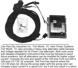
If the design of an alternator depends on a
particular stator wave form and you change it by using a poor
aftermarket reproduction, you are asking for problems for you
and your customers. If an alternator, however, is designed to
survive with high positive peaks and you add an improved wave
form such as the CS-type, you will be providing a superior product
with little increase in cost.
Also, be aware that the concave surfaces generate
a higher frequency component that translates into greater core
loss. If a lower quality core is used, expect more heat and shorter
diode life.
Rotor pole pieces must be of very soft iron
construction. You cannot do any machining to a rotor without generating
hard spots. These hard spots act as permanent magnets increasing
the minimum output current, i.e., your alternator will always
overcharge.

Tossing a rotor into a rotor bin is begging
for a return; like the stator core, rotors should be treated like
fine china. The soft rotor pole pieces are another trade-off as
hardened steel should be used to withstand the centrifugal force
in a rotor that is rotated above 20,000 rpm.
On one hand we want a lightweight, hardened
steel rotor to survive high speeds. On the other, we want a heavy
pole piece, soft iron rotor for both high output range and current.
We can’t have both so the best compromise must be found. Rotating
harmonics also enter the picture as harmonic oscillations can
cause a perfectly balanced rotor to fly apart. Most stock rotors
have an ample amount of pole metal due to the mechanical requirements
of the rotor.
Here is a simple trick to learn how much reserve
a stator-rotor combination has. With ample size rectifier diodes
installed, feed the output of your test alternator directly into
an ammeter shunt that is a direct short. Run your alternator at
6,000 rpm while increasing field voltage from a lab-type power
supply. The current you read on the output should be in exact
proportion to the externally applied field voltage.
As long as the output current increases linearly
with field voltage, you are not saturating either the rotor or
the stator core. You may find that in some conservative alternators,
you can increase the field voltage of a 14.5 volt field well over
20 volts and still see a change. Other alternators will flatten
out at 15-16 volts.
It is the ampere-turns of the field coil that
determines the magnetic force of the rotor. Remember that we must
keep the air gaps constant when determining the field strength.
If you can’t increase the output current by increasing field voltage,
you need more metal in either the field, stator or both. The power
output increases by the square of the stator cross-sectional area,
but it is proportional to the pole piece area.
The final stages in alternator stator-rotor
design are testing and tolerance determination. Testing does not
include running your design on a test bench for a few seconds
to see if you are getting your output current. It does, however,
include operating your design constantly under full-speed and
output range, and measuring the cores and wires for temperature
rise noting any hot spots.
Temperature rise can be measured at room temperature,
however, the rise is added to the maximum ambient temperature.
Most applications require reliable operation at ambient temperatures
ranging from -40° to 130° C. This temperature must be
lower than the breakdown temperatures of your components.
The weak components are the insulation varnish
on the magnet wire, the junction temperature of the main diodes,
and the melting temperature of the bearing grease. You can obtain
these values from your parts vendor. You must also check the expansion
of your materials from the coldest to hottest temperature to be
sure there is no binding.
Once your prototype unit is completed, your
next step is to establish production tolerances using a worse
case analysis. Designs that cannot be manufactured without minor
variations that always seem to occur are useless. Other items
such as shaft and bearing size, slip rings and brushes, rectifier
diodes and heat sinks are left to the discretion of the designer.
Practically all alternators depend on some type of fan cooling.
The thermal resistance of heat sink material can be decreased
by over a factor of 10 by blasting air on it. Voltage regulator
design is too complex to even cover in a series of articles. I
suggest you contact a reputable manufacturer that may already
have a design that could be adapted to your needs.
Whether you plan on designing a new alternator,
modifying an existing one, or just plan on standard unit remanufacturing,
the material presented in this article should give you a good
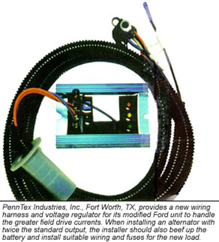
start. The photographs included with this article show what other
companies are doing to accommodate special needs. Read the captions
for further details.