During the last couple of AERA Shows, a seminar on machining a relatively unknown material called Compacted Graphite Iron (CGI) has drawn an interested and growing crowd. The first year’s seminar was the first many had heard about this material and some may have left wondering if this material was headed to their shops any time soon.
Then at the latest AERA RPM show in Indianapolis, the Show Guide had what looked like a typo – another CGI seminar with the same speaker, David Woodruff, who is a process development engineer with Makino. But, in fact, it was no typo; it was a continuation about the cutting technology from where the discussion had left off since the last show. Apparently the cutting technology and processes required to machine CGI are developing that quickly.
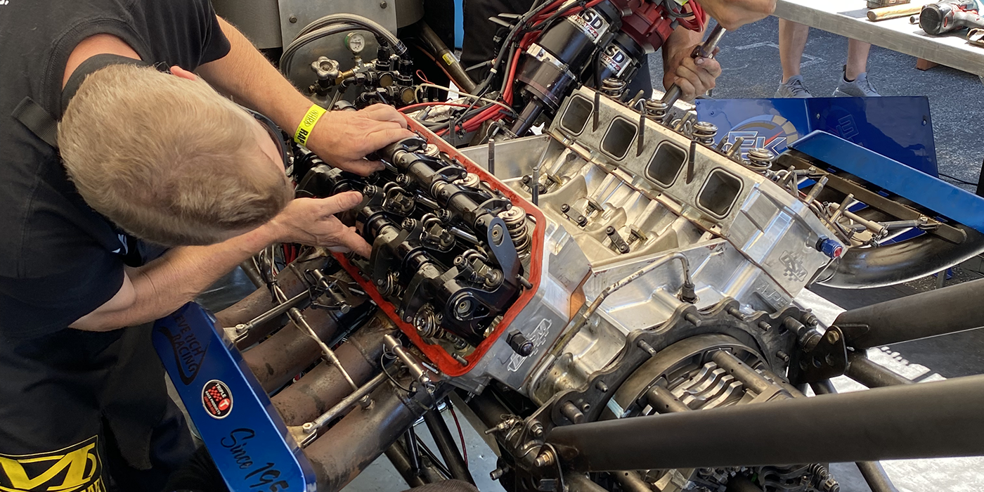
There is great interest in CGI from manufacturers these days because of its strength, which can produce lighter weight castings and withstand high loads (i.e., perfect for diesel engines).
In 1949, a now well-known material called ductile iron was patented. At the same time, a lesser-known material called Compacted Graphite Iron (CGI) was also patented, although it was only considered a curiosity at the time. Compared to gray iron or ductile iron, CGI falls in between these two with regards to material strength.
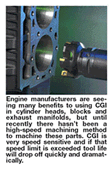
Gray iron is used extensively in cylinder blocks because it’s easy to machine, has good vibration dampening, good thermal properties and low production cost. However, due to gray iron’s structure it’s not as strong as CGI.
The basic difference between CGI and gray iron is the shape of the interconnected graphite matrix. In a CGI matrix, the graphite is more compacted and rounded in what is referred to as “vermicular” or “worm-like” in shape.
When magnesium is added to gray iron in its molten stages the graphite shape changes to a compacted flake. During the casting process, magnesium, which is a nodulizing element, must be maintained at precise levels between .010% and .012%.
However, because the magnesium properties had to be so closely maintained or the entire casting would be scrapped, until recently, CGI was considered too volatile for mass-production. While ductile iron went on to become a staple in manufacturing, CGI was put on the shelf and virtually written off despite possessing some very interesting properties.
This precise control of the magnesium can be aided when titanium is used as an anti-nodulizing element between .1% and .2%, as it increases the ability to produce CGI with higher levels of magnesium present. The drawback to using titanium is that it creates hard inclusions, making it much less machinable. This is why titanium should not be used for producing cylinder blocks or heads.
While not quite as strong as ductile iron, CGI is 75 percent stronger and up to 75 percent stiffer than gray iron. It’s five times more fatigue resistant than aluminum at elevated temperatures, and twice as resistant to metal fatigue as gray iron.
The nodularity and tensile strength of CGI has been found to increase as wall-sections decrease, which have most recently been found to make CGI well-suited for engine manufacturing, where lighter and stronger materials are needed to absorb more power.
Theoretically, a CGI engine block can be fabricated that will be lighter than an aluminum block for equal power densities. Class 8 heavy-duty diesel truck engines are about six times heavier than equal displacement gasoline engines, so the potential for total weight reduction is even greater.
Many OEMs already have engines containing this material or they have plans to produce one in the future, so chances are very good that engine builders will see this material in the future if not already. And since CGI rough machines very well, there is the potential that some grinding operations may eliminate other semi-finish operations, which will in turn save time in the overall process, and bring the cost down to a competitive level.
Continued research and testing, which is already being carried out by several companies, will have a tremendous impact on CGI machining for years to come. Makino is not the only company developing solutions for CGI machining, however for purposes of this article we will concentrate on what Makino and their tooling partner Sandvik Coromant have developed so far.
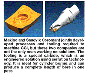
The tooling developed by Makino and Sandvik Coromant is a special carbide Long Edge Tool, which is an engineered solution utilizing serration technology and is ideal for finished mill cylinder boring of CGI. This is due to its ability to produce a complete length of bore in one pass. CBN, ceramic and other special tooling cannot be easily used on CGI because of the lack of sulphur in the material’s microstructure.
A new machining process (jointly developed by Makino and Sandvik Coromant) has been tested and proven based on Makino’s patented “Flush-Fine” machining process in combination with tooling that allows for the elimination of the semi-finishing boring operation.
Last month, Makino’s David Woodruff and Sandvik Coromant’s John Depies hosted a “Machining CGI” Webinar (which is essentially a cyber seminar with the ability to take questions and show presentation slides). We decided to log in for a little note taking and to fire off a few of our own questions as well as listen to the discussion.
What machining parameters can now be realized when milling CGI?
Typically what you find there is something more along the line of ductile speeds and feeds. You’re going to have to keep the speeds down and then you will have to optimize the feed rates as much as possible with the structure that you have because if you bring more inserts to bear to remove the material, then you’re stuck with these additional forces.
How important is the percentage of titanium content in the material?
It’s very important, because just a small change in percentage of titanium in the CGI can halve your tool life. In the case of an engine block you’ll typically have much lower titanium content. Titanium is good for abrasion wear or thermal conductivity. So in the case of an exhaust manifold you’d have a very high titanium content and miserable tool life. But you don’t have a lot of machining involved in an exhaust manifold. With an engine block you want to optimize everything more for milling and drilling because that’s the bulk of the content. With a cylinder head you could probably see some titanium content there as well. But again, controlling that very precisely is important, so that the tooling guy and the process guy know what to expect.
What other automotive components use CGI material currently, and will this material be used more in future applications?
CGI is commonly used in exhaust manifolds, and also some of the large truck manufacturers use it for drum brakes; it works very well for drum brakes. One of the first commercial applications was for the braking systems in high-speed trains in Europe. We also have a very large CGI user in the U.S. that makes power-steering pumps. It’s got very high titanium content and therefore a pretty miserable product to machine because the tool life is very low. But they need the titanium for better wear resistance in the part.
I think as people get more comfortable with CGI and more experience with it, that it will likely move into other areas. I can see that happening. It has a cost premium associated with it from the materials side and the manufacturing side, but the market drives everything in the end. If I have the packaging restraints and the power restraints then I need to have a material that will work with that.
How did Sandvik Coromant optimize the coatings for CGI tooling?
John Depies, Sandvik Coromant: We originally started out using gray cast iron coatings as a starting point, but coating technology has changed so much over the last year. I’d have to say we’re still in the process of developing a specific coating for that. I guess we’re going down the PVD coating road right now.
What amount of stock does the boring tool leave for the hone?
We’re still optimizing that. It’s typical to what you would see with a normal finish-boring tool, but the volume of stock is less even though the radial amount may be roughly the same. The volume is less because of this cultured-type surface that we have. That’s why I mentioned how we can reduce the number of strokes for the finishing operations.
How well does diamond tooling work for boring, honing or milling CGI, and will ceramic also work?
Diamond does work for milling, but you have a severe speed penalty there. So we didn’t see that as a viable method for the milling process. It’s possible to use PCBN tooling for rough boring but then you are stuck with a speed limit there and you’re still stuck with insert density. Consequently, we think we have a faster solution for these processes. However, the verdict is still out on ceramics. We think there may be some potential areas to use ceramics but right now we’re not really actively pursuing that.
There is talk in Europe about using PCD tools for finish boring. Have you heard anything about this?
I know of one company, Mapal, that has a PCD solution for finishing cylinders. Although again, we just think because of the speed limitations there, it’s obviously working, but we think we can do it a little bit faster. We’re looking at the total process that we want to do, not just an individual process. But we look at what can we do for the entire process to make sure that all operations are balanced right up to the honing process.
Why don’t you do circular interpolation when rough milling the cylinder bore?
Originally it was our intention to do that, but when we ran our first tests that process generated such a pile of chips so fast that it kind of made you step back from the door. And this is the problem; because when we cut this dry we generate a load of chips so quickly that we’ve got a big smoking pile of chips laying in the part. From a process standpoint, this isn’t good because the heat will then transfer into the part and you’ll get positional problems. That’s why we decided to go back to conventional style boring and work on optimizing that to improve the results so that our finish mill has less work to do.
What about spindle power during rough boring?
You’re kind of limited on typical automotive bore sizes and you can only package so many
inserts into the tool. So the real factor is not so much horsepower as the stability of the cut and then the thrust of the axis to have the amount of thrust in the axis to push the tool through the part, and then the stability in the fixture in the table to withstand those cutting forces.
Can you elaborate more on the ‘Flush-Fine’ machining process?
The cutter engagement has a whole lot to do with what’s going on. If you think about it as a duty-cycle we’re maybe down in the 5-15 percent range. The tool is maybe only in the cut for 5-15 percent of the revolutions of the tool, so it has all this extra time to cool. Then there is the actual cutting geometry and the cutting edge and the way we advance the cutting edge; it actually produces a very unique kind of chip. In the case of our normal Flush-Fine, in die-mold machining, it’s actually a small crescent style chip, and you use a radiused insert. Then you get your speed of the cut back because of the chip thinning effect you can run at a much higher feed rate. So that’s why you see when we take those revolutions and in a couple of revs this thing is finished much faster than a normal boring process with one or two teeth in it.
Has your bore mill process been used or tested on aluminum engines with CGI liners?
No, not yet. We are waiting for someone to send us one of these so we can test it. We have done some tests on conventional gray iron and on some ductile iron with iron blocks, but not on aluminum with CGI liners. But it would be interesting to see how it works. I really wouldn’t anticipate any serious issues though.
Should interrupted cutting be done wet or dry?
Right now we’re conducting tool life studies, wet and dry. I’m personally not convinced about the best way to go with this type of engagement. In normal flood type operations it is usually a disaster in milling and you’re better off doing it dry. And that’s how we’ve proceeded at this point, but I’m not convinced about that because of the type of engagement. And because of our experience with Flush-Fine, we’ve done it wet and dry and had good success both ways. We are doing this at a higher scale than our die-mold works so the verdict is still out on that.
Do you change the hone abrasive specifications from gray iron to CGI?
Yes, the honing stones are different for CGI. Initially we did use just gray iron stones to do our initial testing. We anticipated that we would have a lot of problems, particularly with loading because of the nature of the structure. You get much more graphite out at the material than you get with your normal gray iron. But because we ended up reducing the number of strokes so drastically, we really didn’t see any problem with that. But we do need a slightly different configuration to get the finish specification that the customer requires. So, consequently, since everybody’s specs are just a little bit different, the whole thing would have to be tuned to your specific requirements.
Is there a risk of greater drill-walk when doing deep-hole gun-drilling?
I would say yes that could happen. It would have a lot to do with the actual material your drilling and your specification. If you try to push on it too hard, you’re going to have problems. Or if you have any kind of casting flaws where you’ve got some local hard spots.
With CGI you have to be careful, one of the advantages of it is because of the chilling effect on thin sections, your nodularity goes up. So if you had any changes in sections that you go through local characteristics could be drastically different and may cause some problems.
What can users expect for drilling tool life?
John Depies, Sandvik Coromant: The drilling tool life is still in experimental stages, so I would have to say that I don’t really have a good answer for that compared to the other types of materials we use currently.
What I’ve found with tool life in some of the drilling that I’ve done is you’ll see a 10 or 20 percent reduction in tool life. But typically, most of the drilling is not for a long duration. So with good coolant supply, you will still take a bit of a tool life hit, but not too severe. And there are some geometries being developed specifically for CGI. One of the most radical is one where the corners are radiused. The problem with that is you still have to generate a pilot hole for it, so it’s maybe not the most economical situation. Mostly in your general purpose drilling it’s not going to make that big of a difference.
What is the best coolant to use with CGI?
It’s really a personal preference as to what coolant you should use. We’ve been trying to utilize full synthetics that so far we’re pretty pleased with. But many times this is dictated by what type of setup you have. If you have a central system you may want to use one specific coolant, and we would have to adjust all the parameters to deal with that specific coolant.
What degree and type of filtration do you use?
Right now we’ve just been using 10-micron filtration on the machines. Most of the operations we’ve had we haven’t seen any problems because of that. Our level of testing, however, doesn’t begin to approach that of what you’d have in a production environment.

