No one knows airflow better than the legendary Joe Mondello, who rose to fame back in the 1960s for his race-winning cylinder head work.
“Back in those days, we didn’t have flow benches to test our work. Our test bench was the drag strip. If a modification worked and made the car run faster, that’s what we used. If it didn’t work and the car ran slower, we went back to Plan A or tried something else.”
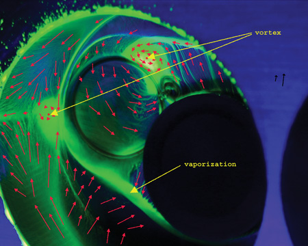
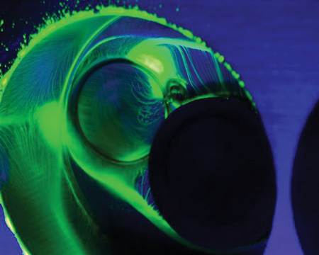
Today, it’s an entirely different situation. Mondello’s tech center in Crossville, TN, uses state-of-the art equipment to test and verify cylinder head modifications. Mondello says most of the development work he does today involves using a wet flow bench, a machine that mixes an ultraviolet dyed liquid mist with air to simulate what actually happens to the air/fuel mixture as it flows into the combustion chamber.
A dry flow bench measures airflow in cubic feet per minute (cfm), which is useful information for evaluating how changes that are made in the configuration of a port or the angles on a valve seat affect airflow at various valve lifts. But a wet flow bench shows you how those changes affect turbulence in the air/fuel mixture, and where fuel may be separating or puddling in the valve bowl, seat area and combustion chamber.
In other words, a wet flow bench shows you things you can’t see with a dry flow bench. It also allows you to verify the effect any modifications you’ve made are having on the air/fuel mixture that might hurt performance because of turbulence, fuel separation or puddling in the combustion chamber. The basic idea is to make sure the air/fuel mixture stays mixed and disperses evenly as it enters the combustion chamber so it will burn properly and produce maximum power.
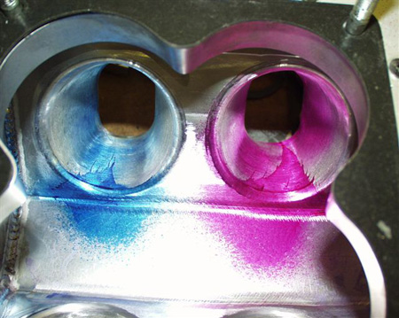
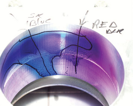
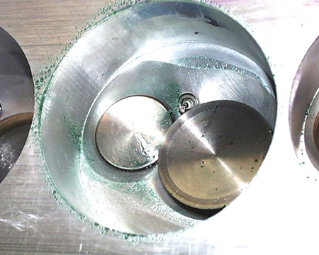
“It’s important to remember that the engine is the primary guide for what kind of modifications actually produce more power, not just airflow numbers alone,” says Mondello. “That’s where the wet flow bench has really helped. The results we see on a wet flow bench are confirmed on the dyno and on the track. We can tear down an engine and look at the patterns on the pistons to confirm what the wet flow bench already told us.”
How Seat Angles Affect Airflow
Generally speaking, the more angles there are on the seats, the better the seat flows. A stock valve seat with only a single 45 degree angle cut on it will have a sharp edge just above and below the area where the valve sits on the seat. As the valve starts to open and air begins to flow past the valve, the abrupt change in angles create turbulence that reduces air velocity and flow.
This abrupt angle can also cause the air/fuel mixture to separate. So cutting another angle above the primary seat and a third angle below the seat helps smooth out the airflow. That’s why a traditional 30-45-60 degree three-angle valve job produces more power than a stock valve job. The extra angles help the air turn the corner so-to-speak, which reduces turbulence to improve air velocity and flow. It also lessens air/fuel separation to improve combustion, too.
Mondello says the traditional three-angle valve job is old hat in today’s performance engines. A 30-45-60 degree three angle valve job is still better than a single 45 degree cut on the valve seats, but it can’t come close to what’s possible by optimizing the valve seat profile with additional angles.
“A few weeks ago, we had three engineers from Harley-Davidson Screaming Eagle Division here for a technical session. They just designed a new 103 head and a 110 head and were quite proud of how well it flowed. We took their head, and in three days time we improved the airflow 52 cfm over their initial design. Out of the 53 cfm that we picked up, 25 cfm was due to changes we made in the valve seat angles alone. That shows you how critical valve seat angles are for maximizing airflow and power,” says Mondello.
“Many cylinder head manufacturers are using single point cutters on a CNC machine to cut their valve seats, and they are not spending much time blending the chambers or doing all the things they really should be doing to make the valve job work properly. That’s actually good for our business because we rework a lot of these cylinder heads, especially Harley heads,” Mondello explains.
The most important part of building any performance cylinder head is cutting the angles on the seats, Mondello says. “Over the years, many engine builders have relied on the basic 30-45-60 degree three angle cutter. They think they can use the same three seat angles on every cylinder head they do – but that’s not true. The angles that work best will vary depending on the application.”
Mondel says he prefers to use a fairly steep top angle, because a steeper angle improves airflow. “When the valve first opens, a steeper angle allows better flow into a combustion chamber that has hills and valleys and is not perfectly flat. If you have a 30 degree top angle, the air coming off that seat will be turbulent and you’ll get separation between the air and fuel which hurts power. Increasing the angle allows for a better transition from the seat into the combustion chamber. It’s more efficient, offers less resistance and makes more power.”
Mondello recalls that in his early days of reworking cylinder heads, he discovered that four angles often provided the best airflow, throttle response and power. The four angles he used were 45 degrees for the primary seat, a 33 to 37 degree top cut, a 58 degree undercut below the primary seat, and a 70 degree cut below that made with a hand-driven reamer. Using these angles can often improve airflow 8 to 15 cfm or more.
Finding the angles that work best with a given cylinder head, camshaft and valve combination requires a lot of time on both a wet and dry flow bench, as well as dyno testing and track time. A lot of small shops don’t have a flow bench or a dyno to do development work and testing on their engines. They have to rely on experience and feedback from their customers to determine what works on the track or drag strip. Consequently, they may not be getting as much power out of their engines as they could.
Special Valve Seat Cutters
To address this issue, Mondello has put his nearly 50 years of experience in reworking performance cylinder heads into his own line of high performance valve seat cutters. The “Joe Mondello Signature Series Infinite Flow Valve Seat Cutters” feature all of Mondello’s tricks for improving airflow, velocity and power. The valve seat cutters feature multiple valve angles that are proven to significantly improve airflow and power over a single angle or three-angle valve seat cutter. Mondello says his multi-angle cutters typically increase airflow 10 to 20 cfm by just adding and changing the angles on the valve seats.
However, Mondello urges caution and care when using a cutter that is designed for a certain application. “My exhaust seat cutters go from a primary seat into a full radius below that seat, but they’re only recommended for exhaust seats, not intake seats. A lot of guys will also use them to cut the intake valve seat because it shows an 8 to 10 cfm increase in airflow on a flow bench. But when you look at the actual airflow pattern on a wet flow bench, the profile that was developed for the exhaust seat causes bad fuel shear and turbulence in the valve bowl and seat area. That’s why I offer different profiles for the intake seats.”
Of course, putting a radius on the intake seat is nothing new, and a lot of guys have been doing it for years because it increases airflow. But Mondello says bigger airflow numbers don’t necessarily translate into more power. It depends on what happens to the air/fuel mixture as it enters the combustion chamber.
“My valve seat cutters are designed to improve airflow, throttle response and horsepower, and they can be used on heads for street cars as well as a race car. Either way, you’re going to get better results than a simple three-angle valve job,” he says.
Mondello says that when cutting a full radius on exhaust seats, it is better to use a seat with a straight ID rather than a seat with a taper ID. With the straight ID, you can form the full radius up to the primary seat without having to worry about running into the bottom taper or leaving a ridge at the bottom of the seat. “I use an 86 degree radius undercut blade (IFT 86R6B-HP) to cut the very bottom of the seat and to clean out that little ring or any deformation that might be left from the seat cutter.”
Mondello’s product line includes a new exhaust seat cutter for heads with smaller valves like those from BMW and Audi, and will soon add a cutter for the intake seats. He also has cutters specially-designed for Harley intake and exhaust valve seats.
Besides making more power, cutting additional angles on the valve seats allows a shop to charge more for a valve job. “It’s a value-added service that improves performance, so why not charge more for it?” asks Mondello.
Important Ratios
Another factor that has a huge impact on airflow through the valve port and seat is the ratio of the size of the valve opening to the size of the throat area just below the base of the valve seat (as measured from the largest area at the bottom of the valve seat). The number one rule here, says Mondello, is having the optimum ratio that maximizes air velocity through the “primary choke” area in the valve bowl just under the seat.
“A lot of the aftermarket performance heads today are typically made with a 91 to 92 percent throat area, which, in my opinion, is too big,” says Mondello. “To get maximum velocity and airflow, the ratio needs to be a little smaller. On many heads, a throat dimension-to-valve size percentage of 86-1/2 to 89 flows best. On Harley motorcycle heads, we use 89 percent. On big displacement high flow V8 racing heads with valve sizes from 2.100? to 2.25?, we may go as high as 90 to 91 percent. We try to keep the choke area as small as we can so it will flow efficiently and improve velocity in the port runner.”
He explains, “If you have big ports in a cylinder head but only a so-so valve seat, the head won’t flow as well as it could. Engines run on velocity, not cfm airflow numbers. The right valve angles will have a supercharging effect that really helps ram more air and fuel into the cylinder. That’s what gives you instant throttle response instead of a bog when you stomp down on the gas pedal.”
Mondello says a bowl cutter should be used to achieve the proper percentage for the valve-to-throat dimension size. Even if a performance engine has to run under a “no porting” rule, the bowl area under the seat can be cleaned up to improve airflow. Reworking this area can often improve airflow an additional 8 to 14 cfm.
Is Good Quality Valve Work Possible With Outdated Equipment?
Mondello chastises shops that are still using old, worn-out equipment to do what they call “performance” valve jobs. “It isn’t really performance work if the equipment can’t hold tight tolerances,” he says. “A tolerance of a couple thousandths of an inch is not close enough when performance valve work requires holding tolerances to tenths of a thousandth. The valve-and-seat machine bearings and pilots have to be in good condition.”
The concentricity of the valve seats to the valve guides is critical not only for proper valve seating and sealing, but also for the longevity of the valves. Misalignment between the valves and seats forces the valve stem to flex every time the valve seats. Eventually, this can lead to metal fatigue and valve failure. So the seats have to be as concentric to the guides as possible.
Mondello said the valve guide pilots that some shops use have too much play for accurate valve work. A valve-to-guide tolerance of .0004? is too much for performance work. It should be down around .0002? or less. One way to achieve that is to use a high-pressure lubricant on the pilot. Mondello prefers a lubricant called CMD-3, which can handle up to 50,000 psi. The same lubricant can also be used on a dead pilot to take slop out of the valve cutting system.
Chatter is another problem that can ruin a performance valve job. Chatter can be caused by three things: too much play in the pilot (or to the guide if the valve-and-seat machine uses a live pilot versus a dead pilot) or the speed of the cutter. However another culprit may be the casue and have nothing to do with the pilot or the cutter: examine how level your machine actually is compared to what you think it is.
“If your valve-and-seat machine is off-kilter just a bit, the valve seat cutter can chatter when it cuts the seat,” Mondello explains. “When was the last time you leveled your machine? More importantly, when was the last time you leveled your level?”
The Living Legend continues: “Many people don’t know that a level is not flat on the bottom. It has a bow in it. Most people also don’t know how to check their level. You can’t accurately level your valve-and-seat machine if the level you are using is off. When you set your level, make sure the little level is always to your left. If you turn it around, you will get a different reading.”
Mondello says using a lubricant when cutting hard seats will also reduce chatter. He uses a 2020 Mondello Signature Series cutting fluid for this purpose, and 2030 Mondello Signature Series fluidwhen refacing titanium and stainless steel valves.
Seat Materials
The type of seat material used will depend on the application. Racers running titanium valves typically use a beryllium-copper alloy seat, or one of the new beryllium-free copper-nickel alloys. Beryllium-copper and copper-nickel seats have a high rate of thermal conductivity, and are a must for high revving, high power engines with titanium valves.
Mondello says one of his favorite materials for valve seats is powder metal. He says he uses powder metal seats from a leading U.S. manufacturer in many of the heads he rebuilds. He likes the powder metal seats for a variety of reasons: they have great machinability when they are new, they produce very little chatter when you cut them, they have built-in lubricity for the valves, they hold up well, and they are made in the USA.
Mondello urges engine builders to be very vigilant about their suppliers, because in his opinion, not all manufacturers pay close enough attention to their alloys. Consequently, the hardness of the seats may vary greatly even within the same size seat.
Interference Fit
Keeping the seats in is just as important as the angles that are cut on the seats. Mondello says one of the most common problems he sees are engine builders not using the proper press fit when they install valve seats. “You should always preheat aluminum heads and freeze the seats prior to installing them (Mondello does not recommend preheating iron heads).
I recommend .005? to .0065? of interference when installing seats in a cast iron head, and .0065? to .007? in an aluminum head, unless the seats are Beryllium Copper, in which case I recommend .004? to .0045? of interference fit. Some guys tell me .007? to .0065? of interference in an aluminum head is too much. But you know what? I’ve never had a seat drop out, not even after an engine got too hot and overheated.”
Mondello says to achieve a good fit, you need a good hole (correct dimensions, smooth finish and no distortion or damage to the seat counterbore). You also have to use a lubricant when driving in the seat.
“I don’t believe in using locking compound on valve seats. It interferes with the heat transfer. All you need is a little assembly lube,” he says.
Mondello says shape is important too. “The valve seat should also have a chamfer on the bottom edge. If you’re finding your seats are straight cut with a flat bottom. You need to put a bevel on those seats before you install them. And regardless of what type of seat you are installing, always use a pilot and driver. Some guys will just beat the seats in using a driver and a puck. That’s asking for trouble. Use a pilot to align the seat so it goes in straight.”
Mondello cautions against using excessive heat when preheating a cylinder head to install new seats. “You only need to heat the head up to about 160 to 180 degrees F. If you get it too hot, say 200 to 250 degrees F, the guides can move around and change the alignment between the guide and seat. When we do Harley heads, we preheat the head on an electric stove. You can also use a hot plate or a torch for the same purpose.”
To be sure, Mondello urges precision. “Use an infrared thermometer to check the temperature. We put the seats in a freezer while the head is being warmed up. That makes it very easy to install the seats. You can almost drop them into place.”
Mondello says you have to install the valve guides before you do the seats. The position of the guides determines the position of the seats, so once the guides are in place, they can be used to pilot the position of the seats.
“On Harley heads, we drive the valve guides into the head from the top (from the spring seats). On most other V8 heads, we also drive the guides in from the top (spring seat side). On early 396/427 Chevys where the guide exhaust guide is stepped, you have to drive out the old exhaust guide from the combustion chamber. New intake and exhaust guides can then be driven in from the top side.”
The key to performance valve work, therefore, is knowing the angles, having a valve-and-seat machine that’s in good condition and can maintain tight tolerances, and paying attention to details.