Having been around the auto machine and engine rebuilding game for 36 years, I have seen changes both good and bad. When I opened my own shop in 1990, I became the 10th auto machine shop in our county in Southwestern Pennsylvania.
A few of these places concentrated on either diesel or high performance, but every one of us did whatever came in the door, keeping all 10 shops (mostly one or two employees) very busy. This was in a low population area (total Fayette County population is approximately 133,000).
As engines became more reliable and the oil and fuel became cleaner, everyday vehicles began to see more than twice the service life without major engine work. The small one and two-man engine machine shops almost suddenly went away leaving specialty and niche market shops to thrive in the new environment.
I had been around antique cars and drag racing since I was a kid, and riding and drag racing Harleys since my early-20s, so in the early years of running a full-time shop I went after those sections of the local market. As things started to change in our industry, it became clear that being able to do specialty work would keep the lights on.
Ernie Cerini acquired the local Harley-Davidson dealership in 1996 and began sending his engine machining to us right away and soon Ernie and I started talking about racing.
I didn’t know it at the time but this would be the start of a small but far-reaching Harley drag racing venture that eventually changed the whole direction of Gregg’s Machine Service as it became GMS Racing Engines.
I had a good deal of experience doing freshen ups and repair on mountain motor drag race engines, blown alcohol hemi engines, and some dirt track stuff in addition to doing crew work and service for a couple of IHRA teams. This was a good foundation for building the V-twin business and pursuing the racing game in the American Motorcycle Racing Association.
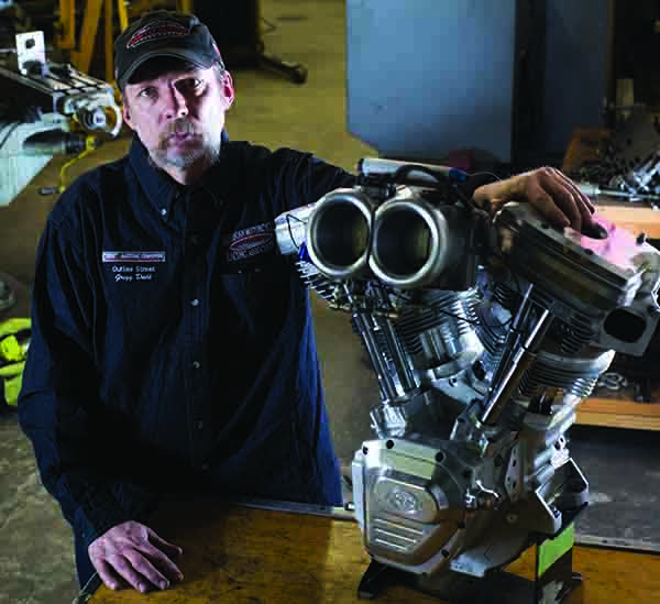
Since going full on into the V-twin motorcycle market we have had the opportunity to do many different types of engine projects. What we will be covering here is a general overview of the most common practices and procedures we use in servicing and rebuilding Harley-Davidson engines and things that are unique to V-twin.
As with any repair or rebuild, a manual with specifications and procedures is one of your most important tools. In the auto world, of course, we have AERA as well as factory and aftermarket resources. Among the best sources for motorcycle information are factory H-D manuals – they are very detailed and include clear photos and special tool listings. Factory parts manuals are also of importance because they have excellent exploded views of parts and assemblies.
Interviewing the Customer
The first task at hand is talking to the customer to get a clear idea of why they want to have work done. If you will be doing a rebuild to address some kind of mechanical problem, it is important to know how the problem arose and how long the engine has been under-performing. Questions like “Did this issue happen all at once or did it escalate over time?” can be very important when it comes to giving the customer back a product that meets or exceeds expectations.
Performance enhancement work requires a completely different interview. Just as important as knowing what the customer expects is knowing how he will be riding the bike – or more importantly how he will treat it. I always stress that there is a BIG difference between performance or racing and outright abuse! All of us in the motorcycle world know that there are customers out there that could destroy anything, so learn to spot them. I have had plenty of clients tell me up front that they abuse their machine so we make sure they know where responsibilities lie and that there may be compromises built into the job to help it survive, IF we take the job at all.
Another red flag is a customer with unrealistic expectations. The web is an awesome tool, however, there is a lot of false information, especially when it comes to dyno charts. My advice is to be sure that your work is represented honestly. We get a dozen or so clients a year that bought the latest “wiz bang super high flying” engine package only to be very disappointed in the product.
I know bringing this up can be controversial but I want to stress how important it is to be a straight shooter and not to get caught up in some internet propaganda war. Make sure to do an accurate estimate and let the customer know right away if there are any changes during the job for any reason. Do a good job, know your client (and be sure he knows what he is getting for his money), know your work and like your work and you will be around for a long time. It is good for you and our industry.
Teardown and Inspection
In our world it is very common to take in engines that have been worked on previously and in most cases modified. Be sure to look for problems like mismatched parts, signs of faulty repair and of course, outright abuse.
It is a disturbing trend that we are seeing engines built with extremely high static compression ratios and a relatively early intake valve closing. This makes for a high dynamic compression ratio that usually requires racing fuel. These combos can read good on a motorcycle dyno but in the field, in customer’s hands, end up coming in with detonation damage.
Most dyno shops do acceleration pulls where the wheel on the motorcycle accelerates a steel drum with the computer reading the rate of acceleration. With the inherent high, flat torque of the V-twin, this method does not load the engine as well as the brake horsepower method (holding the engine steady state to read Brake HP). This, in my opinion, is why we are seeing these detonation-prone engine combinations. When the rubber hits the road, or the track, a properly designed package will outperform these dyno queens any day.
When going through this stage, you will have a chance to see what condition the engine is in as well as seeing problems that may not have been known beforehand. A lot of our experience from doing auto stuff is important here.
When removing the heads, pay attention to the force required to loosen the head bolts. A good portion of head gasket leaks can be traced to a cylinder stud pulling the threads out of the case. The light effort felt breaking the head bolt loose will tell you which one it is right away.
Piston tops can tell us if there is oil getting past the rings by having a clean top near the cylinder wall. Pinched ring lands are a sure sign of detonation as well as scuffed skirts. If you will be reusing the flywheels and connecting rods you can use a wrist pin sized shaft that is long enough to go through the wrist pin bushing and lay across the case decks to look for rod bends. While you’re at it inspect the rod bushings and wrist pins. This is not usually an issue but wear here can be a sign of extreme combustion temps. Evidence of this can also be seen during the piston inspection.
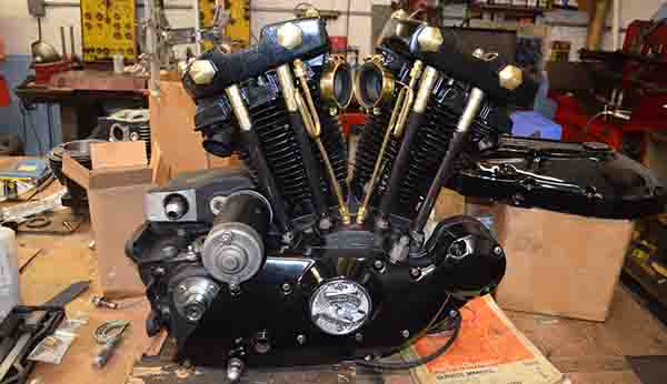
There are several different versions of the H-D V-twin that differs mostly in the gear case where the cam (or cams) are. Evo, Shovel, Panhead and Knucklehead engines are single cam, the Twin Cam is just that, and the Sportster along with several versions of the flathead engines use four cams. The Twin Cam uses a dual chain drive while the others are gear driven.
The first thing to note is the condition of the lifter rollers. There are kits to replace the roller assemblies for most older engines. Replacement lifters are also available for most all V-twins. Be sure to use correct motorcycle lifters! The Twin Cam and later sportsters have automotive style tappets that are metered for the V-twin. Since these are roller bearing engines (Crank, rod and main) they do not require high oil pressure and do not use lightweight oil. Auto tappets will starve the valve train. Always inspect EVERYTHING in the cam case even if you plan to replace it all. Any wear or damage is just more information you have for your customer as well as alerting you to areas that may be improved.
The bottom case splits in two with a right and left half. Once the seal is broken, (usually RTV or case bond) the right side pulls off easily. With most engines, the flywheel assembly will have to be pressed out of the left case half. There is a Timken tapered bearing on the sprocket shaft not unlike the one used for automotive pinion gears. There are spacers between the races and the cones to set the bearing endplay. Save these parts to refer back to. Any 1957 and older big twins and 2003 and newer Twin Cams have big needle roller bearings here and come apart without a press. We convert the Twin Cams to the Timken style bearing whenever we get the chance (more on that later).
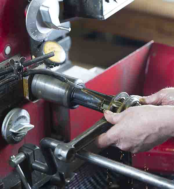
The flywheels or crankshaft assembly on EVO and earlier (before 2000) big twins and Sportster 2002 and earlier use a crank pin that is tapered where it goes through the flywheels and held in place with large nuts threaded onto the ends. These are rebuilt by most traditional V-twin shops. Later engines use a press-together crankshaft that requires a large press and preferably a guide fixture to assemble. Inspect and measure the crank pin and the rod bores. I run the rods around my AG300 gauge to look for run out and taper. Some flywheels have bronze thrust washers on either side of the rod assembly. These can be removed and replaced as well.
Cylinder Heads
After the heads are disassembled we wash off the oil, glass bead the ports and chambers and rewash them in solvent, then hot water. Most of the recon work here is very close to doing air-cooled aluminum automotive heads. Usually, the valve guides do not show much wear in EVO and later engines. When wear is found, look for scuffing or galling on the valve stems. A lean tune can cause excessive combustion temps causing this and a rich tune will cause carbon build up on the exhaust stem and wear the guide.
The port end of the guide must be clean on the OD so it does not gall when it is removed. If the guide seems like it is hard to move in the head, we use one of our old guide and seat machines to bore it thin to relieve some of the press fit for easier removal. Then we clean the guide bore and measure it for the new guide. I like to use .002˝ to .0025˝ press fit for most all aluminum heads and slightly less for iron heads. There are several oversizes available to deal with worn or damaged guide bores. We hone galled bores back to true and then install the proper guides. We then use a carbide reamer to size the new guide according to factory specs. A touch up with a hone for “bringing in” the size is ok if you need the extra clearance. Performance work here can warrant different clearances but we will discuss another time.
To do the seats I have a Serdi 100 that was rebuilt by Jamison Equipment to meet my needs. I use a 1.500˝ thick aluminum plate machined to accept two heads side by side. It makes for a nice, rigid, easy-to-use setup.
There are valve stem height specs to be aware of also. You can find valves in the aftermarket to deal with this or replace the seats as necessary (common in performance builds) should the job stray too far from spec. Since the rocker arms are a common assembly, you must pay attention to the stem heights to insure that the geometry is satisfactory. There are rocker box spacers and various gasket thicknesses to help here when doing performance work.
We do a light resurface with our PCD/CBN equipped surface mill and wash for assembly. Be sure to check valve spring pressures and travel. If you have your stem heights correct, the spring fit will be easy. Then we assemble with the proper seals. Before the mid ’70s seals were not used in a lot of these engines. Check your manual to be sure.
We do quite a bit of head porting and flow work for the V-twin market. H-D heads respond very well to mild valve oversizes and mild port work. It’s something to consider when getting into this market.
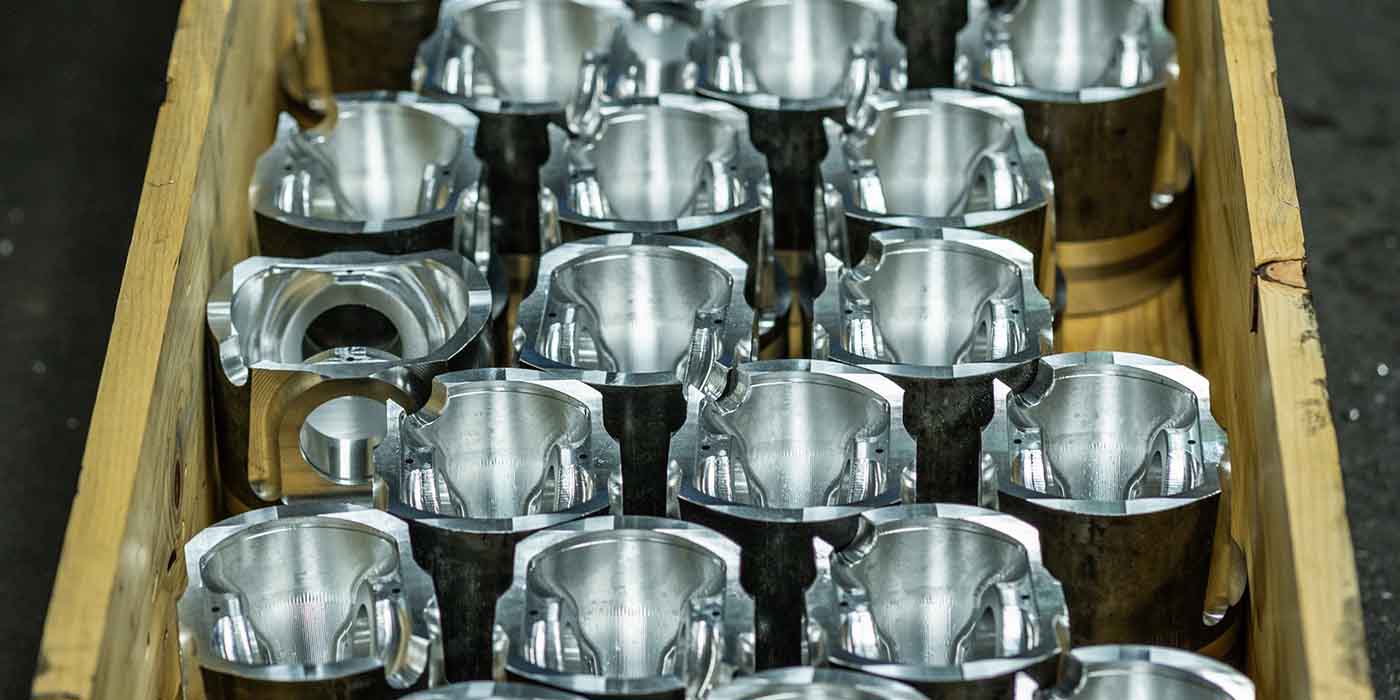
Cylinders and Pistons
Pistons for the V-twin market are plentiful to say the least. Oversizes in .005˝, .010˝, .020˝ and .030˝ are common for later twins and up to .090˝ for 74 cid Shovelheads. A popular mod on 88 and 96 cid Twin Cams is to bore the cylinders .125˝ over to bring displacement to 95 and 103 respectively. Boring and honing with the correct torque plates is a standard procedure.
On some engines that have had some heat scuffing, the spigots that extend into the case can be distorted or worn WAY out of round. On .005˝ and .010˝ over jobs we have been able to straighten the spigots by manually rough honing them on a Sunnen horizontal hone and pushing down on the tight spots in the spigots as you hone. This may not be “standard practice” but we have had good results doing this. Practice on some old barrels to get a feel for it and you may save a few cylinders in the future.
There is also a wide range of “Big Bore” kits on the market; some are drop on and some require case boring. When using big bore or “stroker” pistons it is a good idea to fit the crank into the left side case half and add the cylinders and pistons to turn things around to check for case clearance and piston-to-piston clearance. When the pistons touch on the bottom of the stroke, I trace the outline of the rear cylinder bottom relief cut (the cylinders are each cut at 22.5 degrees to meet each other at the bottom) onto the rear piston skirt with a scribe. Then, with the piston upside down in a piston vise (I made mine from a lathe chuck) cut across the skirt at 22.5 degrees until the cut gets to your scribe mark. Next, I tilt the piston to 45 degrees and bore through the cut (at bore +.050˝) until the cut reaches the outside of the skirt. This way both major thrust skirts are left intact.
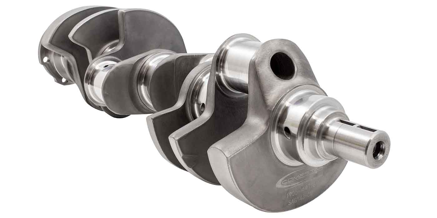
The Bottom
Servicing the flywheels requires an acquired skill as well as some special tools. Earlier I talked about the tapered crank pin in EVO and earlier models and how it is held in place with large nuts on either side of the flywheels. We loosen the nuts and then strike the flywheel on the outer edge from the side with a large copper hammer and then do the same to the other side. The taper will jump free and you can then disassemble the crank.
On flywheels with replaceable main shafts, nuts and tapers are here as well. They can be loosened by backing off the nuts to get about .040˝ gap between the nut and flywheel surface and then striking the center of the shaft within the nut with a hammer and a soft drift. If the tapers look smooth and clean then new shafts can be installed, trued and torqued to spec. These days replacing the connecting rods is a popular option but we also rebuild factory rods either by honing the races for oversize rollers or by replacing and fitting new races. Oversize crank pins in .001˝, .002˝ and .003˝ are also available.
Balancing the assembly is both simple and complicated. S&S Cycle sells a very complete tool kit for doing this which we use to get very good results. This is a static procedure that may sound primitive but, if done correctly, will produce excellent results.
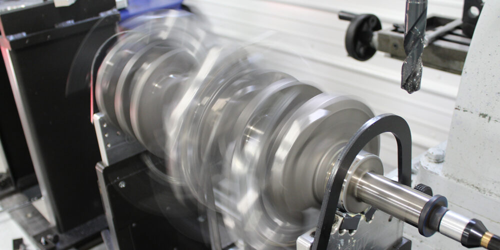
After the assembly is together and slightly snugged up, we move on to a truing stand (between centers in a lathe works fine too). There is a truing procedure in the factory manual that describes this in great detail. Without getting too deep, we bump the wheels around on a large block of maple with a large hammer and an aluminum bar so as not to mar the flywheel outer surface, progressively tightening the crank pin nuts as we go back and forth from the block to the truing stand.
We have a couple of fixtures fabricated to hold the assembly for torqueing. There are various specs for torque so once again consult the manual or the crank pin and shaft manufacturer. This is one of the few jobs I know that needs a BIG hammer to get .001˝ adjustment. I’m convinced this procedure is better learned by experience than taught. Get some old wheels and practice!
Twin Cam and late model Sportsters have a press together crank, which can be similarly serviced, but as stated earlier, requires a large industrial press. Most shops that service these units machine away the center of the crank pin so as not to gall the bore in the flywheel when disassembled. A large rigid alignment fixture is also used for assembly.
EVERYTIME the gear case is opened up on these engines, check for run out at the end of the pinion shaft with a dial indicator. Some late TC engines have a .012˝ max run out spec but we like to replace the assembly at .005˝ to .006˝. There are complete, ready to install units available from several different manufacturers, which makes replacement as good an option as rebuilding.
To assemble the crank and cases requires setting up the Timken dual cone bearing in the left side of the case. There are special tools to pull the inner bearing cone onto the sprocket shaft as well as installing the spaced races into the case. There is also a spacer between the bearing cones to set endplay, usually .001˝. Twin Cam engines have a large needle roller here with endplay set using large heavy shims or thrust washers that we remove and replace with a conversion sleeve to allow the use of the stronger cone style bearing. Then, after endplay is set, the left case is placed over the crank and the outer bearing cone is pulled into place. You will most likely have the case pulled onto and off of the crank a few times to get this right. The right case is mated to the left with a thin layer of ultra silicone or case bond product.
There are Twin Cam engines in some models with a balance shaft and chain arrangement that runs below, fore and aft of the flywheels in the cases. They are not difficult to service but require special attention and tools. Note how they come apart and refer to the manual for assembly.
Gear (Cam) Case and Top End
There are different procedures for assembling the gear case on each of the different engines. Big twins from 1970 through the end of the EVO era are quite simple. Setting endplay for the camshaft and breather gear is done with shims specific to each part. Before 1992, the pinion gear, which drives the camshaft and breather, fits over the end of the pinion shaft onto a keyed taper held in place with a special nut. Behind the gear is a spacer, then a keyed, floating worm type gear that drives the oil pump. These gears require specific tools for removal and installation.
After 1991 the EVOs had a slide-on pinion gear making service a little easier. The breather gear mentioned earlier is a timed rotary gear that has a window that lines up with an opening in the case as the pistons move to BDC and closes as they move up to TDC. When shimming aftermarket cams for proper endplay, be sure to check that the tappets have some side clearance with adjacent lobes when on the cam’s base circle.
Take care when assembling and installing the oil pump on these big twins. There are two sets of gears for both pressure and scavenge and tiny keys that fix the drive gears to the shaft. These can come loose during installation. I always install the pump before the pinion gears so I can turn the pump after it is tight against the case to make sure it turns free and is working properly.
Sportster cam cases use four cams that all require end play attention. For consistent results, the correct gasket must be used on both engines for the gear case cover when end play is checked.
The Twin Cam gear case has seen a few changes since its first incarnation. The first version uses a link belt type chain that drives the cam set that is in turn connected with the same style of chain. Earlier twins used the gear cover to support the outer cam bearings/bushings. The TC has a cam plate for this that also acts as pressure control and distribution for the oil pump that bolts to the inner side of the plate and fits over the crank’s pinion shaft much like the Chevy LS pump. There are spring loaded chain tensioners on each chain that had some wear and failure issues.
Later TCs have a hydraulic tensioner system with roller chain cam drives that is much more reliable and can be used on the early TC. Also, S&S Cycle offers a gear drive system that works well for high performance use. As I said before, it is very important to use tappets specifically designed for the V-twin.
After hanging the pistons on their respective rods (always full floating with wrist pin clips), you can install the cylinders, being careful not to break any rings. I like to use a band-and-pliers style ring compressor and a bit more chamfer on the bottom of the cylinder than is used atop an automotive one. There are both head gaskets and O-rings (sealing the passages that drain oil back to the case) for the head to seal. There are a few different head tightening methods ranging from standard torque to torque to yield, but it’s best to follow the recommendations from the gasket manufacturer.
Just as a footnote on EVO and later engines: most all methods will get you around 40-foot-pounds final torque. When installing the rocker boxes on any model be sure to look for friendly geometry and clearance problems especially with large aftermarket cams and springs.
We always discard the non-adjustable pushrods and replace them with quality adjustable units from S&S or Smith Brothers. Follow the lifter manufacturer’s adjustment procedure and be sure to allow ample bleed down time before moving on to the next one.
There are books and manuals that contain hundreds of pages of information detailing the service, modification and rebuilding of the H-D V-twin. What I wanted to bring to you here is an outline of what is required to service these engines. I hope that a few of you will consider this market as something that could help to grow your business and help to keep our niche in the market a busy one.