Understanding Compressive and Tensile Loads
Many consider the connecting rod one of the hardest working components in an engine, and there doesn’t appear to be too many lining up to dispute the claim. Connecting rods are subject to constant stress through extreme tensile and compressive loads, each one tied to a different aspect of operation.
As the tachometer climbs, so does the tensile load on connecting rods. The tensile load is effectively trying to pull the rod apart, and it’s the tensile strength of a connecting rod that determines the maximum stress it can withstand. In addition to piston speed, contributing to tensile load is the mass of the pistons, rings and wrist pins, as well as the stroke of the crankshaft.
Tensile load is based upon inertia, so naturally a lighter piston and rod assembly reduces these forces, but since rod strength must always be considered, the lightest rod isn’t always the right choice. Often lighter, shorter pistons with heavier, stronger rods are chosen.
Tensile load is reduced by the cushioning effect of compressing the air/fuel mixture, but this force doesn’t exist on the exhaust stroke, and is lost when the throttle snaps shut, cutting off airflow to the engine during deceleration. For this reason, rods often fail when the throttle is released at the end of a run down the dragstrip.
Compressive load, or the force pushing downward on the rod, occurs as a result of combustion, but is part of a complex calculation of displacement, rpm and horsepower. If you compare two engines that make the same horsepower at different rpm, a greater compressive load occurs in the engine that makes more power at a lower rpm.
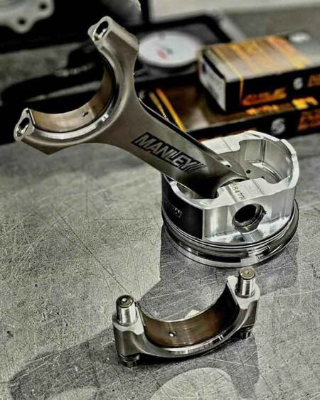
All these factors are taken into consideration and influence rod design, but first and foremost, you need substance.
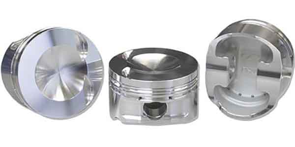
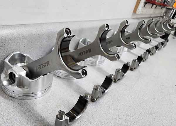
“Placing the proper amount of material (cross sectional thickness) in the appropriate (highest stress) areas, is a main factor in rod design,” says Trip Manley of Manley Performance.
Research and undoubtedly plenty of trial and error has allowed rod manufacturers to narrow in on exactly where the high-stress areas of a rod are located.
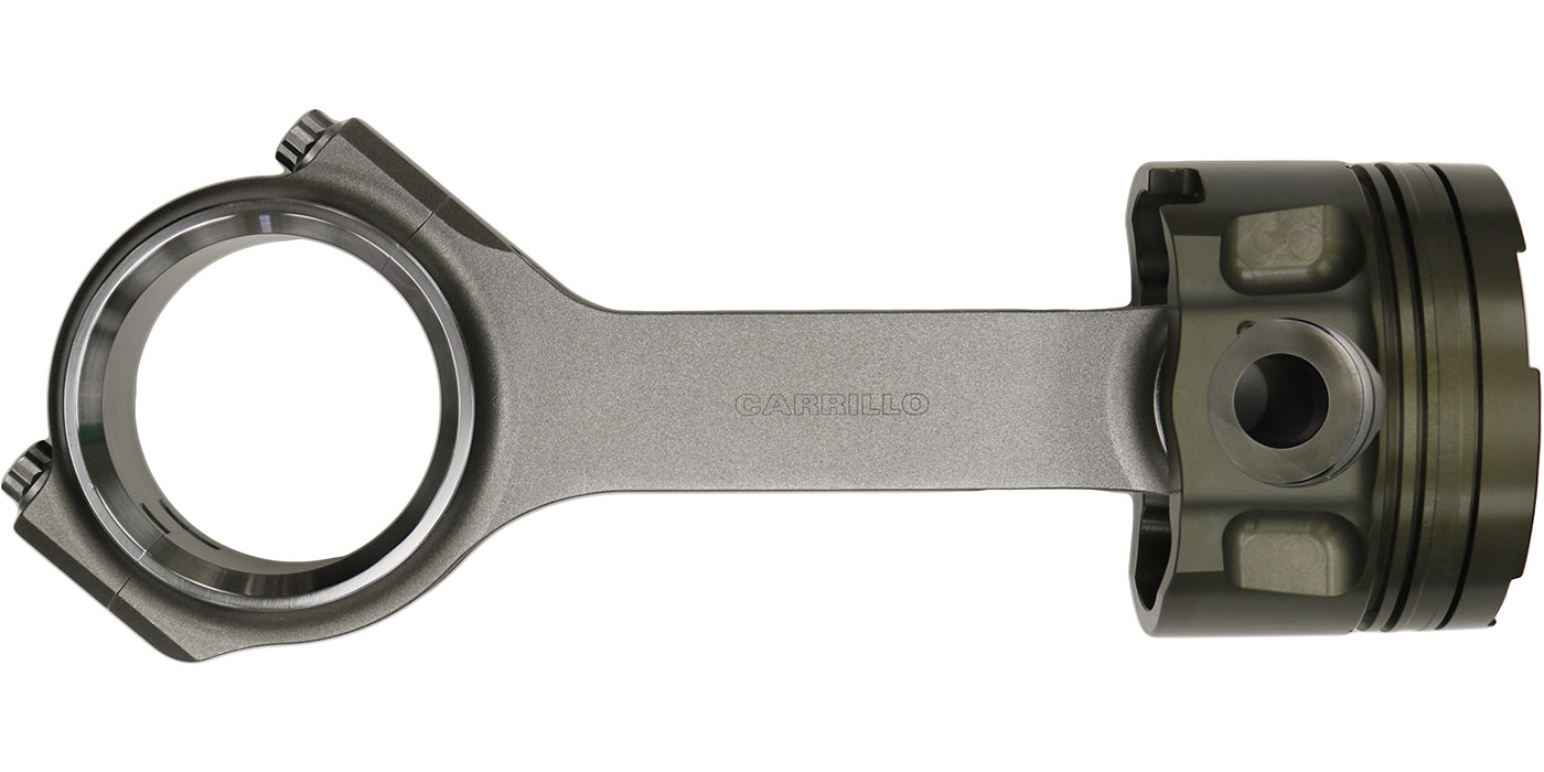
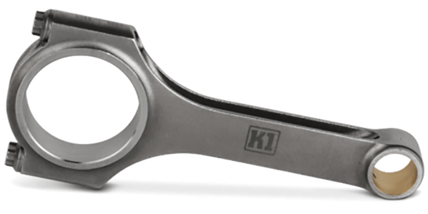
“Having the correct cross-sectional areas in the critical areas of the rod, which are the strap above the pin, the beam, the cap and big end neck between the bolt and beam, are the main factors in rod design,” says Cindy Verkooij of CP-Carrillo. “These are the areas that see the majority of the stresses. To determine the inertia and compressive loads we want to know the engine operating parameters among other details – bore, stroke, max horsepower, rpm of max horsepower, and piston assembly weight. If the customer knows peak firing pressure this can be useful for the compressive loads part of the design.”
The science of compressive and tensile loads may be one of the more complex subjects of engine building. The most interesting factor is you can’t select a rod based on horsepower alone. When selecting a connecting rod, the main consideration is are they suitable for the horsepower and rpm of the engine and the application they are being built for?
“Just because a rod is designed for 1,000 hp in a 650 cid engine does not mean it is safe for 1,000 hp in a 400 cid engine,” Verkooij says. “The smaller engine is working harder to make the same horsepower and is putting the parts through higher loads. Another example is a 1,000-hp rod designed for all-out drag racing may not be suitable for a 1,000-hp endurance race engine simply due to the cycle loads the engine and parts are seeing. Drag race applications are short-term loads and may only see loads for 8-10 seconds, while the endurance engine may be required to run for several hours.”
In the effort to continuously improve on connecting rod strength and performance, both material and design are factors, but is it an equal focus?
“We use 4340 and 300M steel and 7055 aluminums,” says Bryce Mulvey of BoostLine Connecting Rods. “These alloys have been popular and quite successful for a long time, and while some material process improvements have taken place, the greater focus has been on rod design.”
While proven connecting rod materials are overall consistent, they’re not lost to the idea of ongoing research. The main materials used for connecting rods are steel, titanium and aluminum alloys.
“Depending on budgets and competitiveness in each relevant race or OEM segment, we work with our customers continuously on evolutions of these available materials and heat treatments,” Verkooij says. “Once validated to be an improvement, these will go into more parts over time and phase out the old materials and heat treatments used. Still, many of our materials have been used for many years now, with very small variations in material characteristics over time and very good knowledge of fatigue strengths, Young’s modulus (a mathematical calculation of elasticity), thermal conductivity, thermal expansion at various temperatures, as well as failure modes.
“This allows very refined, lightweight designs custom tailored to the application needs. For any new material, this knowledge will have to be acquired basically from scratch. Revolutionary ideas like carbon fiber, wood or plastics rarely have seen successful operation in the past.”
The forging process, and any related changing science of it, is similar to the use of new materials from the aspect that continuous development is never overlooked but pursued to a limited and cautious degree.
“Forging processes for steel, titanium and aluminum differ significantly from each other due to the different requirements and behavior of these alloys,” Verkooij says. “Forging processes continuously evolve as well, with similar advantages and risks as on the material side. The focus points on the forging process are degree of plastic deformation, material fiber flow, material grain size, surface quality of net shape forgings, 3-D forging of undercut geometries, and raw material usage on near net shape forgings.”
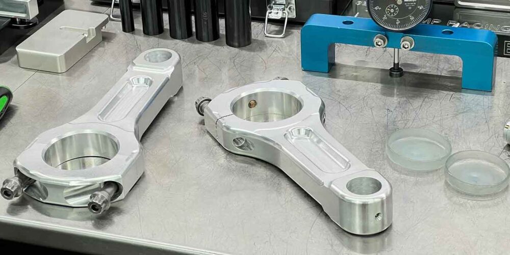
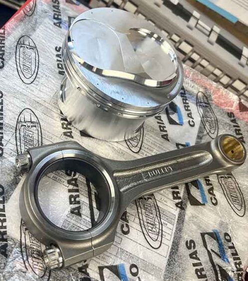
The billet versus forged question is a valid factor with connecting rod design, as with other engine components.
“We do not see billet as an advantage except when you do not have a forging to fit the rod you are trying to make,” Verkooij says. “We prefer a forging over billet for grain flow, grain structure and better fatigue strength, and we 100% machine them from our oversize forgings.”
The choice of billet rods is situational, and expert viewpoints hold similar across the board.
“I wouldn’t necessarily say billet possesses a strength advantage, but it certainly provides us with manufacturing advantages and tremendous flexibility on the aluminum side of things,” Manley points out.
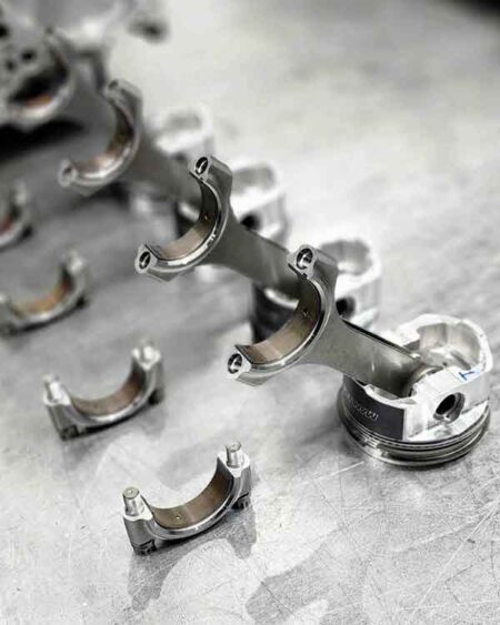
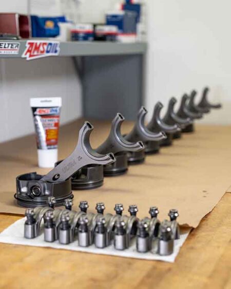
As can be expected, proper assembly techniques are key to avoiding rod failure, and lack of proper techniques can often be blamed when something goes wrong. For one, bearing clearance is critical. If the oil film between the rod bearing and crank journal goes away for any reason – for even a fraction of a second – it can overheat and seize the bearing.
“Improper bearing clearance can cause the bearing to break through the oil film, causing the bearing to spin or send excessive heat to the rod big end, resulting in a failure,” Verkooij says. “Higher rpm and more horsepower usually requires a little more clearance than a stock engine.”
High-quality rod bolts and heeding proper torque procedures are equally important. These days, you cannot just use torque as your only method to assemble connecting rods when building a high-performance or racing engine.
“The number one way to assemble rod bolts is to stretch them the required amount to achieve the proper clamp load as the stretch for a given bolt will remain the same,” Verkooij says. “Torque only measures the forces to overcome the friction of the bolt and rod. If you only go up in 5-lb. increments, the amount of torque lost to just overcome the friction will result in less bolt movement and may not stretch as much as is needed.
“When you stretch the bolts, even if it is 0.001” at a time, it is still stretching the bolt the same amount. When stretch is not possible, the second-best method is torque angle as it uses a preload torque on the bolts to seat cap and bearing and then a set angle of movement to get into the window of the required stretch. Torque angle numbers are developed through repeated testing and verification of how much the bolt is stretching at these recommended angles.”
Occasionally, a new design surfaces, which indicates some possible advantages over tried-and-true designs. One of the more recent is a two-piece connecting rod that is advertised to eliminate side-to-side piston forces, increase torque and boost dynamic compression by 25%-30%. Not originally designed for all-out performance, per say, but is there any possibility for it in this market?
“In our experience, this type of connecting rod design has no benefits due to increased weight, complexity, cost, and no benefits in friction due to an increase in ‘virtual’ piston compression height and shortening of rod length,” Verkooij says.
If connecting rods are truly the hardest working component in the engine, continuously designing and manufacturing them, might be one of the hardest jobs. EB