Valve lifters play a key role in the valvetrain of pushrod engines. They go all the way back to the earliest days of the internal combustion engine. The earliest engines did not have pushrods or rocker arms. They were a “flathead” design with the valves in the block. The lifters (also called “tappets” because of the clattering noise they produced) rode on the cam lobes in the block and actuated the valves directly. It was a simple design but not the best configuration for breathing efficiency or horsepower.
Relocating the valves to the cylinder head was a major step forward in “overhead valve” (OHV) engines because it allowed the engine to breathe more efficiently and develop more horsepower from the same displacement. The overhead valve design added complexity to the valvetrain because it required the addition of pushrods and rocker arms. The lifters also had to route oil up through the pushrods to lubricate the upper valvetrain components.
With “overhead cam” (OHC) engines, the camshafts are in the cylinder head(s) and actuate the valves directly or via cam followers, so there are no lifters. However, most modern OHC engines do have some type of hydraulic valve lash adjusters. The adjuster may be mounted in the head and serve as a fulcrum point to maintain zero lash between the cam follower and valve, or located inside a bucket that fits over the top of the valve, or a “mini-adjuster” mounted in the end of the rocker arm.
The Lifter’s Role In the Valvetrain
The basic function of a valve lifter is pretty simple. It sits on the camshaft and transfers the motions of the cam lobe up through the pushrods and rockers to open and close the valves. The size and shape of the cam lobe under the lifter (multiplied by the ratio of the rocker arms) determines valve lift and duration. As such, the lifter just follows the motions of the cam. But it does play a role in valvetrain lash (clearance) and noise.
In “solid lifter” pushrod engines, the lifter is just a hollow bucket. It has a hard faced bottom that rides on the cam, and a cup on top that supports the lower end of the pushrod. The lifter has an inlet hole in the side so pressurized oil can fill the lifter body, and an outlet hole in the center of the pushrod cup so oil can flow up through the pushrod to lubricate the upper valvetrain components.
With “flat tappet” pushrod engines, the bottoms of the lifters appear to be flat. But actually on most applications the bottoms of the lifters are slightly convex. The center is about .001 to .002˝ higher than the edge. Also, the lobes on flat tappet cams are not perfectly flat but have a slight taper (.0007 to .002˝) to one side. In addition, the centerline of the lifters are offset slightly with respect to the cam lobes. This makes the lifters rotate as the cam turns, which helps to reduce friction and wear.
The area of contact between the lifters and cam lobes is the highest loaded surface inside an engine, with as much as 200,000 to 300,000 PSI at the point of contact depending on valve spring pressure! Consequently, it is critical that both components have the correct geometry (both convex and taper), that both surfaces have adequate hardness to resist premature wear and failure, and that the point of contact receives good lubrication with a motor oil that contains sufficient levels of high pressure anti-wear additive (such as ZDDP).
Lubrication has been a problem in recent years because the amount of ZDDP in motor oil has been significantly reduced to prolong the life of catalytic converters. The zinc and phosphorus in ZDDP anti-wear additive will contaminate the catalyst if an engine is burning oil due to worn valve guides, seals and/or piston rings. Reducing ZDDP to less than 600 ppm has not created a problem for most late model engines because they have low friction roller lifters or overhead cam followers. But in older engines with flat tappet cams, using a low ZDDP motor oil may not provide adequate wear protection for the cam and lifters – especially if stiffer valve springs are installed. The work around is to use a break-in oil that contains higher levels of ZDDP, and then refill the crankcase with a specially formulated “street performance” or “racing” motor oil that contains extra ZDDP. A ZDDP additive can also be used to fortify low ZDDP conventional and synthetic motor oils.
Aftermarket cam suppliers have also upped their game by increasing the surface hardness of their flat tappet cams to make them more wear resistant with today’s motor oils. Some suppliers offer lifters that have a small pinhole burned through the bottom center of the lifter body to direct oil right to the cam lobe. Another supplier grinds several small flats only a few thousandths of an inch deep down the sides of their lifters so more oil can flow down onto the cam.
Roller Lifters
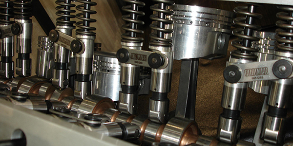
A big improvement came about with the invention of roller lifters. By placing a small wheel on the bottom of the lifter, friction between the cam and lifter is greatly reduced. That’s why all modern pushrod engines have roller lifters. Roller lifter also allow the use of more radical cam lobe profiles with faster opening and closing ramps that allow more total valve opening for a given lift and duration. That’s why roller cams are the hot setup for racing.
Mounting a wheel on the bottom of the lifter also changes the dynamics between the lifter and cam. A roller lifter has to be held in fixed alignment with the cam so the wheel will roll smoothly on the lobe, so you don’t want the lifter to rotate or twist. This requires the addition of a linkage bar between adjacent lifters to keep them straight, or machining the lifter body and lifter bores with a flat to prevent them from twisting.
One of the differences between a roller cam and a flat tappet cam is that the lobes on a roller cam are truly flat whereas those on a flat tappet cam have a slight taper. If the wrong type of cam or lifters are used together (flat tappet cam with roller lifters, or a roller cam with flat tappet lifters), the mismatch will cause bad things to quickly happen.
Something else that should never be done when rebuilding an engine is to install a new cam with used lifters. The cam and lifters develop a specific wear pattern to each other as they seat in. If a high mileage cam is worn, or one or more lifters show concave wear on the bottom, the cam and lifters all need to be replaced.
If the original cam and lifters are still in good condition and are being reused, make sure all of the lifters are reinstalled in their original holes (same location as before). However, if the original cam is worn and needs to be replaced, replace the lifters too. Don’t ruin the new or reground cam by reusing worn lifters.
The only exception to this rule is with roller cams. Because the cam lobes are flat and the lifters have rollers rather than a convex surface, a new roller cam can be installed with used roller lifters provided all of the lifters are in good condition with no damage, pitting or cracking.
Hydraulic Lifters
Hydraulic lifters were first developed back in the 1930s and became common in production engines in the 1950s. Hydraulic lifters eliminate the clatter produced by solid lifters because the valvetrain runs with zero lash (clearance). Solid lifters require a small air gap between the tips of the rocker arms and the tops of the valve stems to compensate for thermal expansion in the engine as it heats up. Lash adjustment is critical because too much clearance makes the valves noisy and reduces valve lift, duration and performance. Too little clearance can also create problems because it causes the valves to open sooner and close later, reducing heat dissipation through the valve seats when the valves are closed. This can make some valves (especially exhaust valves) run too hot and fail. If the lash is way too tight and closes up entirely, it may hold the valve open causing a loss of compression and possibly contact between the valve and piston.
Solid lifters require regular valve lash adjustments to compensate for wear in the valvetrain. With racing engines, valve lash adjustments may also be required to fine tune the engine for prevailing weather and track conditions. Changing valve lash has the same effect as changing valve lift and duration. Less lash increases lift and duration for more high end power, while opening up the lash adjustment decreases lift and duration to improve low RPM torque and throttle response.
Hydraulic lifters eliminate the clatter and the need for periodic adjustments by maintaining zero clearance when the engine is running. They do this by using oil pressure against a spring-loaded plunger inside the lifter body. Oil fills the cavity under the plunger when the valve is closed. This pushes the plunger up to take the slack out of the valvetrain and hold it tight. A one-way check valve inside the lifter holds the pressure inside the lifter as the valve opens. Since oil is incompressible, the oil trapped under the plunger prevents the plunger from compressing and the lifter act like a solid lifter to push the valve open.
Hydraulic lifters are also kinder on valvetrain components than solid lifters because zero valve lash reduces the hammering effect that occurs when the valves slam shut at higher engine speeds. There’s no air gap to fill so the valve simply follows the cam lobe as it closes for a more gentle landing. This also reduces noise and helps extend the life of the valvetrain components.
Under normal driving conditions, there’s no danger of the valves being pushed off their seats or not fully closing when they seat because the valve springs exert more pressure on the valvetrain than oil pressure inside the lifters. But at high engine speeds (say over 6,000 to 6,500 RPM), hydraulic lifters experience some limitations.
At high speed, hydraulic lifters may “pump up” and hold the valves open causing the valves to float. This can happen if the valve springs are not strong enough to maintain normal valve control, and the lifters try to take up the slack that really isn’t there. This overextends the plunger and prevents the valve from closing all the way. The same thing can happen if the oil inside the lifter does not bleed down quickly enough between cycles to maintain normal valve lash.
Hydraulic lifters can also “pump down” or collapse” at high RPM if they are leaking too much oil pressure internally due to sloppy assembly tolerances. This creates too much lash in the valvetrain, which results in noise and loss of power.
Hydraulic lifters are precision fit assemblies. The plunger is closely matched to the housing to provide minimal clearance so the leakdown rate is not too great or too small. That’s why you should never intermix the internal parts when you are cleaning and rebuilding a set of hydraulic lifters. Do each lifter individually so the original assembly tolerances are maintained.
One of the key differences between stock production hydraulic lifters and aftermarket performance lifters is that the latter usually have tighter internal tolerances for better oil control. Many performance hydraulic lifters also have better valving that allows them to handle more RPMs than their stock counterparts. A good set of aftermarket performance hydraulic lifters will typically allow an engine to rev 1,000 RPM higher than with stock hydraulic lifters. Some can handle even more RPMs. Even so, most hydraulic lifters can’t match the performance and reliability of solid lifters over 8,000 RPM. That’s why high revving engines in NASCAR, drag cars and circle track cars still use solid lifters.
Hydraulic Adjustments
Hydraulic lifters still need to be adjusted when they are initially installed so the plunger will operate in its mid-range of travel. If the plunger bottoms out, it may prevent the valve from closing causing a rough running engine and possible valve-to-piston contact. A plunger that is over extended and near its upper range of travel may not be able to maintain zero lash as engine temperature changes. This can increase engine noise, and it may even cause the plunger to hammer against the snap ring causing it to fail.
A hydraulic lifter plunger may also become over extended if an engine has sticking valves or excessive wear in the valvetrain. It can only take up so much slack before it runs out of adjustment.
Something else to keep in mind if you are replacing a set of hydraulic lifters is to make certain the plunger height in the replacement lifters is the same as the old lifters. A difference in plunger height will require longer or shorter pushrods to compensate.
New Lifter Designs
The ongoing quest to squeeze more fuel efficiency out of today’s engines has lead to the development of various “displacement on demand”, “variable displacement” or “cylinder deactivation” technologies on some engines. Basically, the idea is to deactivate up to half of the engine’s cylinders when it is under light load to conserve fuel. Switching off the fuel injectors to kill certain cylinders saves fuel. But if the valves are still opening and closing the engine is wasting energy pumping air through the dead cylinders. The valves also have to be deactivated at the same time to maximize the energy savings.
Deactivating the valves traps air in the dead cylinders. This creates an “air spring” effect that returns almost as much energy on the piston downstroke as is put in during the compression upstroke. The engine squeezes the air during the compression stroke, and the air pushes back as it expands during the downstroke.
There are various ways to deactivate cylinders, including cams that have different lobes for each cylinder, changing the position of the rockers or using hydraulic lifters that can collapse on command to eliminate valve lift. A variable position valve lifter can operate with normal plunger height or reduced plunger height. This requires a secondary oil supply hole and valving to change the position of the plunger inside the lifter.
The powertrain control module (PCM) regulates the oil pressure to the lifters via solenoid valves. With multiple cylinder deactivation, several solenoids may be used to control oil flow to various lifter pairs. Cylinder deactivation adds more complexity to the valvetrain and increases the chance of something going wrong and causing a loss of power if cylinders remain deactivated when they should be producing power. Problems with engine sensors (notably MAP, airflow and throttle position sensors), the oil flow control solenoids, engine oil pressure (if the engine is also equipped with a variable displacement oil pump), the PCM or wiring faults may all affect the normal operation of such a system.
Assembly Tips
When installing a new or reground cam and lifters, use a high pressure cam lube rather than motor oil or general purpose assembly lube to coat the cam lobes and bottoms of the lifters, and use a break-in oil that contains extra ZDDP. The high pressure lube is necessary to protect the cam and lifters following the initial start up and break-in process.
A new cam and lifters can be ruined if not broken in properly. Most require keeping the engine RPMs between 1,500 to 2,000 RPM for 20 minutes. Don’t let the engine idle and don’t over rev it either. The cam and lifters need plenty of lubrication during this period, and minimal stress as the lifters and lobes get to know each other. Final valvetrain adjustments and engine tuning can be done after the initial cam break-in period is over.
Roller cams are more forgiving than flat tappet cams as far as break-in is concerned because there is much less friction. Even so, the engine RPMs need to be kept about 1500 to 2000 RPMs following the initial startup for several minutes to make sure everything is compatible and is getting sufficient lubrication.
Hydraulic lifters will normally make some noise when an engine is initially fired up, but should soon quiet down as oil fill the lifters and the lifters expand to tighten up the slop in the valvetrain. Some experts say hydraulic lifters should be presoaked in oil and bled prior to installing them. Others say this isn’t necessary and actually increases the risk of the lifters holding the valves too far open.
The normal procedure for adjusting a set of hydraulic lifters is to rotate the cam so each pair of lifters is at their lowest position on the base circle of the cam. This is done by rotating the crank so that cylinder is at Top Dead Center on its compression stroke with both valves fully closed. The rockers are then adjusted to zero lash and then given an additional 1/2 to 3/4 turn to push the plungers inside the lifters down to their midrange position. The procedure is then repeated for each cylinder until all the lifters have been preset. If the lifters are prefilled with oil, they may not push down when the rockers are given the additional twist causing the valves to lift off their seats instead.