Hydraulic lifters have been the choice of the automotive industry for many years for several good reasons. When compared to a mechanical lifter, the hydraulics are:
1. Quieter.
2. Low maintenance.
3. Able to adjust for thermal expansion of the engine.
4. Considered as a built in shock absorber, eases stress on valve train.
5. Capable of having a “bleed rate” that can be designed to accommodate different engine rpm ranges.
Mechanical cam designs require a running clearance or valve lash, while hydraulic lifters are just the opposite. When the rocker arm assembly is properly torqued down into position, the pushrod must take up all the clearance and descend into the hydraulic lifter, causing the pushrod seat to move down by .020? to .060? for most applications.
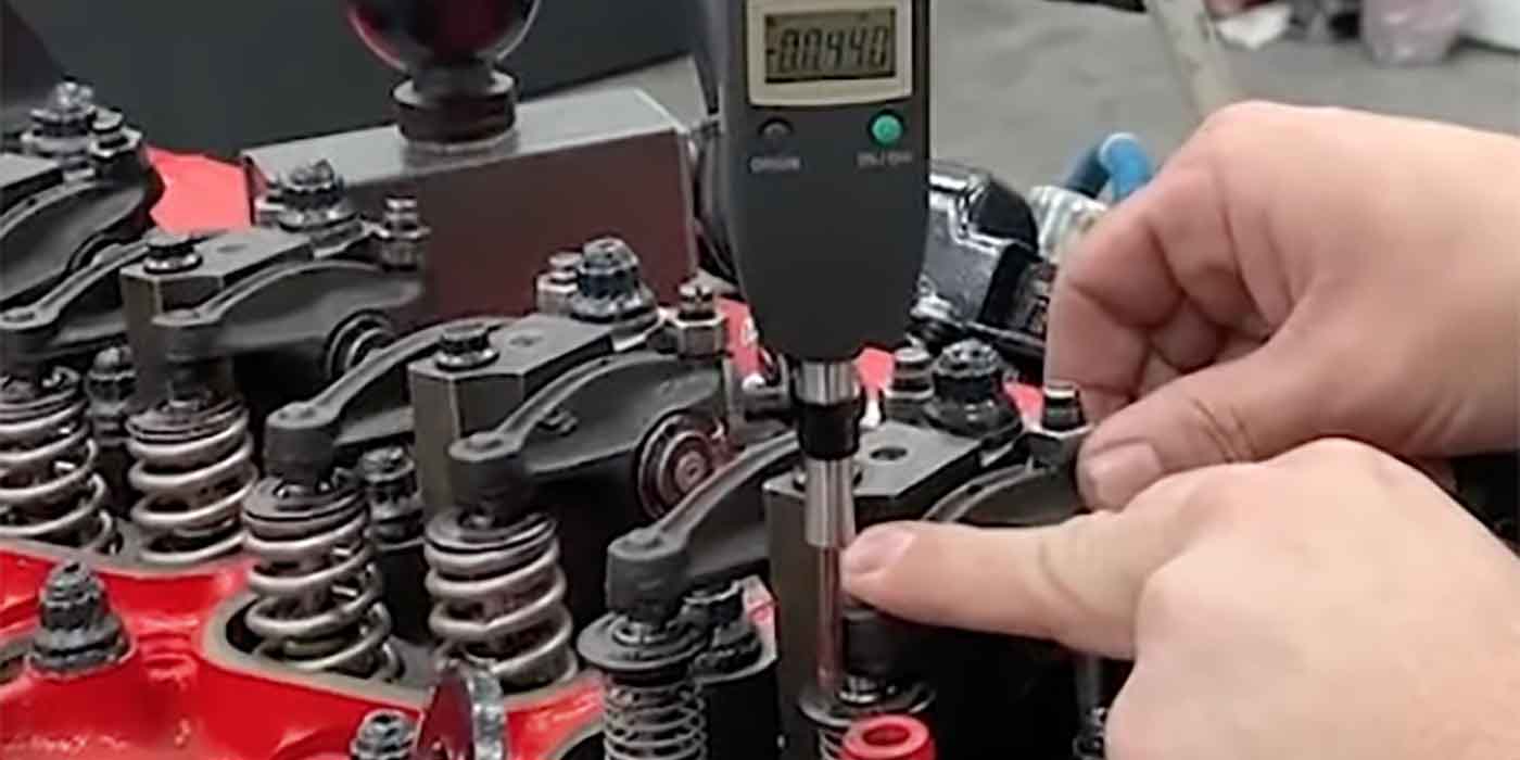
The distance that the pushrod seat moves down away from the retaining lock is the “lifter preload”. The hydraulic mechanism requires this precise amount of preload” for it to do its job properly (see illustration).
There are a couple of notable exceptions to be aware of:
As the LS-series of Chevrolet V8 engines have rather close piston to valve clearances, the preload should be set incrementally, 1/4 turn at a time, allowing the lifters to bleed down between each adjustment. This will avoid the possibility of bent valves.
Another important instance are those engines that are equipped with steel billet hydraulic roller lifters. Due to the strength and stability of these lifters, 1–1/4 to 1–1/2 turns of preload can be used, resulting in a reduced oil volume in each lifter, allowing more consistent operation and stability throughout rpm range.
If clearance exists between the pushrod and the seat in the hydraulic lifter, you will have no lifter preload. In this case the valve train will be noisy when the engine is running. All of the hydraulic force produced by the lifter will be exerted against the lifter’s retaining lock, and this could cause the lock to fail. If the opposite occurs, and the pushrod descends too far with the lifter on the base circle, then you may have excessive lifter preload. This could cause the valve to stay off its seat during most of, or all, its entire cycle. This reduces the cylinder pressure, lowering the performance of the engine. Backfiring may also occur.
Many things can affect lifter preload. If you do a valve job, surface the block or heads, change the head gasket thickness, or buy a new camshaft, the amount of preload can be affected. Sometimes these changes cancel one another out and your preload stays the same; this is more by luck than design. This is why you must always inspect the amount of preload the lifter has when reassembling the engine and be sure that it is correct.
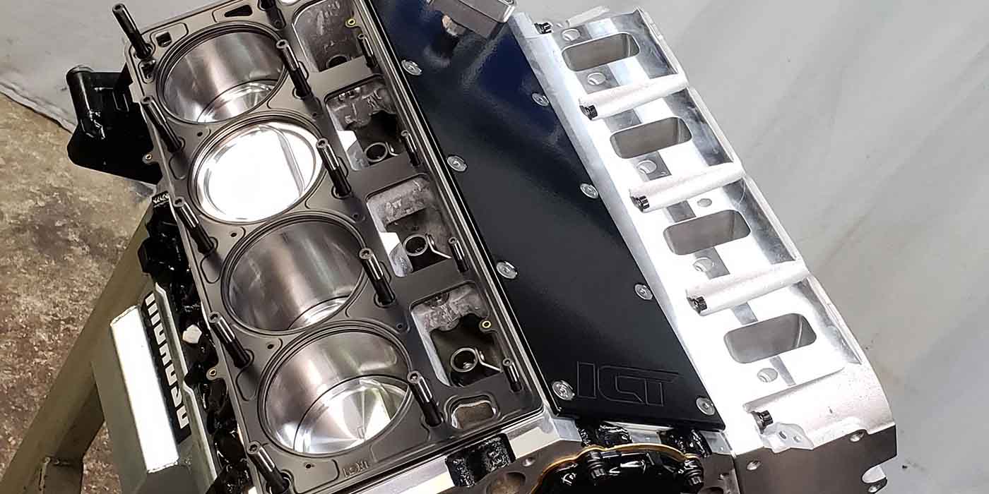
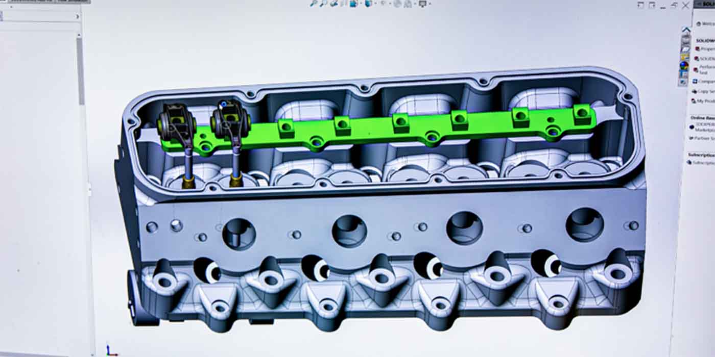
With the cam, hydraulic lifters and pushrods in place, install your rocker arm assembly. Use the prescribed method in your repair manual and torque down all the valve train bolts in the proper sequence. Pick a cylinder that you are going to check. Hand rotate the engine in its normal direction of rotation until both valves are closed. You are on the compression cycle for that cylinder. (At this position the valve springs are at their least amount of tension making the job a little easier to do.) Wait a few minutes, allowing the lifters to bleed down.
Now, lay a rigid straightedge across the cylinder head, supporting it on the surface of the head where the valve cover gasket would go. Using a metal scribe and the straight-edge, carefully scribe a line on both pushrods. Now carefully remove the torque from all valve train bolts, removing any pressure from the pushrods. Wait a few minutes for the pushrod seat in the hydraulic lifter to move back to the neutral position. Carefully scribe a new line on both pushrods.
Measure the distance between the two scribe marks, it represents the amount of lifter preload. If the lines are .020? to .060? apart you have proper lifter preload with flat-faced lifters. If the lines are the same or less than .020? apart you have no, or insufficient, preload. If the lines are further apart than .060?, you have excessive lifter preload. To bring your preload into tolerance, use one of the methods described below.
There are several different methods for increasing or decreasing the amount of lifter preload, depending on valve train design and how the rocker arm is held onto the cylinder head. Automotive manufacturers have made changes to the valve train over the years. What may work on one year’s engine may not work for another, even though they are basically the same engine. There is one method that universally works on all these engines, change the pushrod length!
Use a longer pushrod to increase preload, a shorter to reduce preload. Various length pushrods, and custom lengths are available from aftermarket suppliers.
The easiest method to arrive at proper lifter preload is when you have an engine with “adjustable valve train.” Unfortunately, since 1967 most domestic engines, with the exception of small and big block Chevrolets, have been made with non-adjustable rocker arms.
Since hydraulic lifters can compensate for thermal expansion of the engine, the adjusting can be done with the engine cold; hot adjustment is not necessary.
In order to adjust the preload, the lifter must be properly located on the base circle or “heel” of the lobe. At this position the valve is closed and there is no lift taking place. You will need to watch the movement of the valves to determine which lifter is properly positioned for adjusting.
Many people mistakenly believe that hydraulic lifters must be soaked in oil overnight and be hand pumped up with a pushrod before installing into a new engine, however this is not necessary. In fact, this could cause the lifter to act as a “solid” and prevent obtaining proper preload.
What is very necessary is the priming of the entire engine’s oil system after the preload has been adjusted, and before starting up a new engine for the first time. This is done by turning the oil pump with a drill motor to force oil throughout the entire engine.
Source: Crane Cams 


