The most misunderstood component of an engine is the camshaft. Selecting a camshaft and understanding its profile and design can be a “black art” as most of what a cam profile controls is invisible – air. Yet, the camshaft has a major impact on engine performance.
As we know, the cam profile controls the valve action, but it also controls other fundamental dynamics of the engine relating to performance and durability. The cam profile affects valve action, parts wear, spring breakage, valvetrain component failure/wear, loss of valve control, and parasitic power losses.
Due to the “black art” aspect of camshaft selection, it is most always based on a referral or prior experience, with some folks using various gas exchange software from a basic gas model to very expensive unsteady gas exchange modeling software to develop valve events. In some cases, these empirical valve events are then forwarded to a “cam designer” such as myself and others to mathematically derive a profile to meet the requested events. In some rare occasions, the engine designer will also establish dynamic or derivative controls such as acceleration or jerk limits.
Some customers call for valvetrain distress/breakage problems but have excellent power from the existing camshaft.
Component failure is usually addressed by a redesign of the cam profile as well as keeping the same thermodynamic (horsepower) attributes. This is a common (pushrod) request and usually obtainable.
To understand the terms in profile design it would be required reading and ownership of the late Don Hubbard’s book “Camshaft Reference Handbook,” available at http://books.sae.org/b-966/.
I urge anyone who is in the engine world to obtain this reference book. You will not regret it.
Most engine designers will buy a “shelf” cam that is pre-engineered out of a catalog with a basic description and sometimes with the help of a salesman. This method is most common and satisfies most general design needs. Other folks will have a cam consultant or engine designer provide a “custom” cam, which is more often than not a pre-designed lobe from a cam company’s catalog. However, the minority choose to have a camshaft truly custom designed by either the camshaft company or someone like me.
In this case, the lobe is truly custom and one has the ability to control all aspects of the cam lobe profile such as valve action, forces, dynamics, etc. and the designer must create a continuous curve (no discontinuities allowed) with the proper values to meet the criteria requested.
Design
Typically, today’s cam lobe profile design has been conducted using Polynomials or B Splines. Using these mathematical functions one is able to establish control over at least three derivatives, which control various aspects of kinematic and dynamic outputs.
The derivatives of displacement (lift) are the rate of change of lift over time (cam degrees), velocity, acceleration, the rate of change of acceleration (jerk) and snap – the rate of change of jerk. Ultimately, these derivatives have real dimensional components manufactured into the cam profile.
Lift changes of .001˝ (one thousandths) are not a big deal in the grand scheme of valve lift for airflow. But lift changes of .001˝ per degree have larger consequences in velocity. Lift changes of .000100˝ (one hundred millionth) have a major influence on acceleration. And lift changes of .000050˝ (50 millionth) have large influences on jerk.
One can see that the derivatives can have major changes due to the profile having grinding errors, design discontinuities, or improper lobe manufacturing technique.
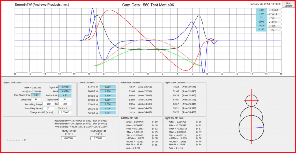
In order to control these dimensions in today’s world we use computer software such as Andrews or 4stHEAD to design profiles – there are other programs but these are the ones I commonly use.
Contrary to popular notion, there really is no concept of designing a lobe by asking for a particular .050˝ duration or .006˝ duration. To obtain those timing points one uses techniques of manipulating exponents as in Polynomials or Spline knots to create a curve that hopefully meets the common cam timing points such as .006˝, .050˝ or .200˝ lift.
This is done by a few or many iterations, which can be a short amount of time or take days to design one proper lobe profile. To make it more cumbersome, a DOHC engine needs four distinctly different lobes to obtain the same valve action across the engine.
Even though one ultimately creates a design that has the proper cam timing, the derivatives that control dynamics and force may be undesirable and that forces one to input another round of iterations to design a proper curve to meet the cam specs and the dynamic constraints. Cam profile design is not for the timid or the impatient.
Cam profile design limits for example are not limited to acceleration, jerk, radius of curvature or pressure angle.
Other limits may be piston to valve clearance, variable valve timing, race or street applications, springs, lifters, thermodynamics, and whether the engine is naturally aspirated, supercharged or turbocharged, which require distinctly different designs and requirements.
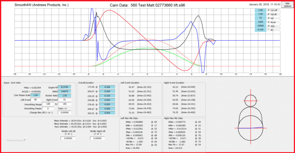
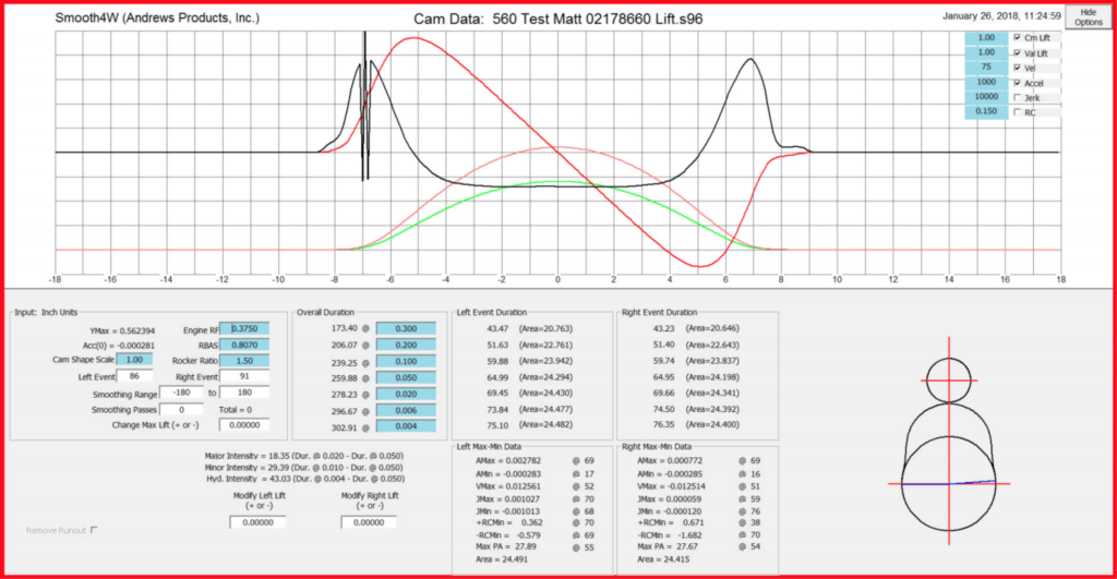
The control list can be endless and is usually predicated by cost or lack of input from the customer. Every camshaft design we offer has either been engineered from scratch or adapted from a previous custom designed camshaft. Our design processes involves a full, 360-valve lift event table and not just “X” lift at “Y” duration. This allows us to precisely control the curvature characteristics of the opening and closing flanks as well as the lobe nose. During the design process, we match the curvatures between the flanks, nose and the base circle in order to have one continuous lobe profile without discontinuities.
In an Overhead Cam (OHC) design, we design the valve action in the software and then create the cam lobe shape by a mathematical function of the valvetrain geometry.
In both translating (pushrod) and OHC finger follower designs we cannot use the rocker ratio for actual valve lift due to the rocker ratio not being constant, but the translating system goes back to the 1950s so we use lobe data and generic rocker ratio to express valve motion.
The engine and consequently thermodynamics sees valve action so rocker ratio is worthless to use for actual engine performance. OEM and high-end pushrod designers use valve action and convert via valvetrain geometry to derive cam lobe shape.
In both OHC finger follower and pushrod systems, if valve action is symmetrical the resulting cam lobe is asymmetrical and open and close are different. In some systems, particularly OHC finger follower, incorrect cam lobe shape results in major changes to valve action in either cylinder banks and creates poor performance at part throttle and wide-open throttle.
An easy example requiring a different cam lobe shape is in a finger follower system when we move the pivot or lifter from one position to the other, another is changing the valve tip height or changing rocker arm dimensions, all changes such as these create large variations in valve action resulting in poor performance or poor low speed operation if the design is for an unmolested valvetrain.
When we have a camshaft design finalized it is then converted to a CNC file and sent off to the camshaft grinder. Our ultimate goal is complete valvetrain control and a design that can be verified against after manufacturing … something that can’t be done with a simple two-event specification.
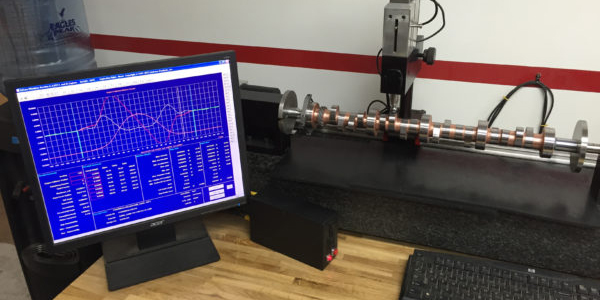
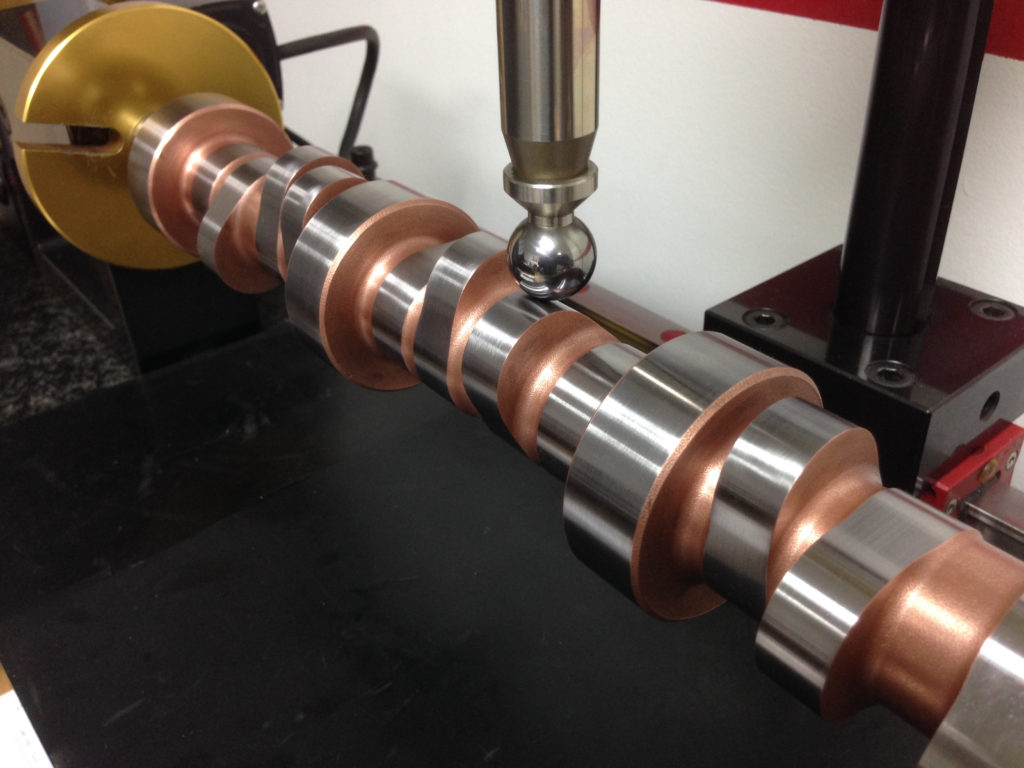
After we have received the camshaft back from the grinder, it is then verified against its design file on our EZCam machine. The EZCam machine is a computer controlled camshaft verification device that duplicates the cam lobe profile to follower behavior that occurs inside an engine. As the camshaft is rotated, a probe is lowered against the cam lobes allowing it to measure the finished profile and compare it against the design file. It will also measure the individual journals and compare them against each other in order to measure effective run out and size. If the finished camshaft doesn’t meet our tolerance requirements (.0005˝) the camshaft is sent back to the manufacturer for a regrind.
Grinding and Manufacture
To properly design today’s high-speed lobes, it requires extremely accurate manufacturing to avoid creating abnormal derivatives. Years ago, 6,000 rpm was a magic number unheard of in engines and that was mostly due to the inability to grind accurate profiles. Today, we have stock OEM engines running 8,500 rpm right from the showroom.
In today’s high-speed world we must have manufacturing equipment that can grind into the millionths of an inch to control jerk. Currently snap control cannot be consistently manufactured.
So what kinds of machines are cams manufactured on? In years past, cams were ground by tracing machines. In the hands of a skilled operator, a very decent profile can be ground, but errors would occur resulting in a poor job of controlling jerk.
Most of today’s cams, particularly OEM and OHC cams, are ground on a CNC machine. Most flat tappet cams are ground on Berco-style machines. Today, CNC controls position the grind wheel to grind lobes with a tolerance of 10-50 millionths, which is .000010˝-.000050˝. That tolerance does a good job of controlling jerk, which does allow high-speed engine operation.
Post Manufacture
After the camshaft is ground it is important that the person supplying the cam to the end user measures the cam for quality control (QC). This QC procedure guarantees that the manufacturing errors (there always are errors – we are human, after all) are acceptable.
Error tolerances are based on the money spent to meet the error tolerance. No surprise, as quality takes time and energy.
In the industry, the QC machine that high end manufacturers use is the Adcole. The Adcole machine is very accurate and is able to discriminate between minute errors based in the design data, but it has a cost typically out of the engine guy’s budget.
The machine that I use, which is much easier to program than the Adcole and meets excellent accuracies is Andrews Products EzCam (www.andrewsproducts.com/camshaft-inspection/key-features).
The EzCam is able to discriminate and compare to the profile design within a very acceptable tolerance for the cam grinder and especially the engine designer. Pictured earlier was L&M Engines fully automatic CNC controlled EzCam, which measures every cam sold by L&M.
The EzCam is well within any cam manufacturer’s budget and if the cam manufacturer does not have the Adcole or EzCam machine they are not able to determine the critical grinding errors that effect engine performance.
There are many other cam measuring machines and one must understand the accuracies needed to properly QC a camshaft before purchasing.
In the end, if one elects to use a “shelf” cam, the results will be within design and budget. If one elects to use a consultant cam designer, his experience and the catalog lobe combinations he specifies will work well if the consultant’s technical skills are in line with the project.
If one elects to use a true cam designer to produce a cam lobe from scratch based on engineered timing events or the designer’s experience of proper valve timing events for the application, the end results will be commensurate with the expense.
That’s Great, but Why Do It?
We are in an industry full of pretenders, plagued with “gut feeling” and “he did so I did” engineering. That’s why we take testing and analysis so seriously here at L&M Engines. Over the last 40 years, we have made it our mission to only offer sound and proper engineering decisions backed up by testing data. We live and die by the scientific method and that’s why we say, “Power is not a guess.”
We find camshaft design and analysis absolutely crucial when designing high-performance engines allowing us to avoid power robbing situations such as improper grinds and bent camshafts. Taking shots in the dark is inefficient and often leads nowhere.
I owe a great deal of gratitude to the late Don Hubbard for our conversations over the years.
I also owe a great deal of gratitude to John Andrews of Andrews Products.
I would also like to thank the engineering staff at COMP Cams.