Tenths Are Not For Camping
I was told a few times that “tenths are for camping” when I was “chasing tenths” in my early machining career. We had micrometers with “tenths” reading on their spindles but the tolerances we had for our “vintage” engines allowed us to be fairly sloppy and still produce what was considered a quality product. Keep in mind though; this was the era when we all walked the 5 miles to school uphill both ways.
There is a big difference in newer engines – today, we can expect engine life of 300,000 miles or more. Early failures in most modern engines can probably be avoided with good maintenance practices. But working on a precisely built modern engine requires measuring in “tenths” as mandatory.
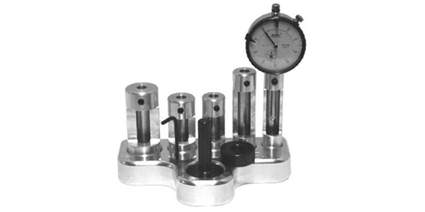
Since measuring in tenths is now a way of life, let’s take a look at your measuring equipment. You must consider that even with the best of care, micrometers, dial indicators, etc. can wear and become inaccurate. Just occasionally checking your outside micrometers with the reference standard that comes with them is not nearly enough to ensure the accuracy you need.
Whether you are using a micrometer for setting dial bore gauges, inside micrometers or snap gauges, you are relying on the micrometer’s accuracy for the size. For example, when you use an outside micrometer to set a dial bore gauge, the bore gauge is used as a “comparator” to establish a tolerance. The exception to this is when some type of calibrated setting fixture is used instead of a micrometer to set a bore gauge.
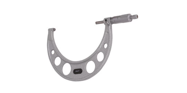
Since outside micrometers are usually what most shops rely on for an accurate dimension, let’s focus on their use and care.
Regardless of the brand or type of micrometers you have, how often do you check them for accuracy with the reference standards that are usually supplied with them? Keep in mind that using your supplied standards is not considered “calibrating” your micrometer. You are just confirming that, by using the standard made for it, the micrometer is accurate at that size. How accurate it is for the rest of the one-inch travel of the barrel should be confirmed by using gauge blocks.
There are lots of published technical papers out there telling you how critical your calibration procedures are. One of my favorites is a paper titled “Calibration Guidelines for Micrometers Using a Five-Point Calibration Method.” Under these guidelines a micrometer that is sent to a qualified calibration lab is first checked for obvious damage and that the barrel runs the full length freely. The condition of the spindle and anvil faces are checked, and any wear of the threads in the barrel is recorded.
To check for thread and barrel wear, traceable gauge blocks are used to measure five different sizes. An example of the micrometer being checked with gauge blocks would be a -0.997˝, +0.611˝, 0.502˝, 0.246˝ and 0.128˝. The different sizes mean that the barrel of the micrometer will be stopped in a different position for each measurement. Any error more than +/- 0.00005˝ would show there is wear on the internal threads of the micrometer. These are not the only dimensions used for calibrating micrometers – most any combination will work as long as you are certain they are accurate and consistent.
Gauge blocks must have a certificate of traceability from the National Institute of Standards and Technology (NIST). This means that they can be used to meet the 4:1 rule of calibration, the common rule of thumb first published in 1960. Gauge blocks are considered the highest in the hierarchy of precision – the accuracy of a gauge block is typically +/- 0.000002˝ and the accuracy of a micrometer is typically +/-0.0003˝. This difference exceeds the 4:1 ratio.
The other area to be checked is the flatness and parallelism of the face of micrometers. You’ll never even notice it by looking but wear on the face of a micrometer from normal use can cause the face not to be flat. Physical damage, like dropping a micrometer, can cause the faces not to be parallel.
Accurately checking the flatness and parallelism is done using an optical flat or optical parallel and a monochromatic light. The optical flat is a specially ground piece of glass that shows errors by using light bars reflecting off the faces of the micrometer.
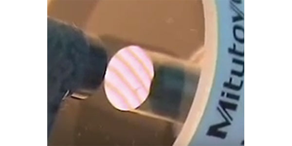
This picture shows a micrometer face being measured with an optical flat using a monochromatic light source. The space between the light bars is approximately 12 millionths of an inch. The straightness of the lines indicates that the surface is virtually flat.
A simpler way for checking flatness is to use a ball or the sphere from a CNC probe. Accuracy matters – the heat from your hands can cause the metal sphere to grow enough that it will give erroneous readings. I have had success determining if a micrometer face is flat by using a tenth reading dial bore gauge. Carefully moving the contact point around the micrometer faces can show if it is dished out from normal wear.
Even companies that have a dedicated gauge department will usually have an outside lab periodically certify their instruments. The cost of traceable gauge blocks, optical flats, the monochromatic lighting and a temperature-controlled room can be significant. But when you add the training and competence of people doing the checking you can see that it takes a very large company to justify a complete in-house lab.
How a shop keeps track of the condition of their measuring equipment depends on many factors, and paying attention to the accuracy of your equipment is paramount to producing a quality product. However, when you add in the human element to doing precision measuring, you should realize you have another variable to work with. An outside micrometer can be used very accurately to get a dimension, but it can also be used as a crutch to confirm a dimension the machinist wants to see. Not only do you need to check the accuracy of the micrometer but that of the user as well.
One method of checking the accuracy of employees using micrometers is to put a piece of tape over the dimension of a gauge block, then have everyone who uses micrometers measure the gauge block and record what they see for size. Once again, care must be used when doing this as just the heat from handling a gauge block can change its dimension. To be more practical, in an average shop you could use a freshly ground and polished crankshaft for checking.
When outside micrometers are calibrated by labs they use the spring-loaded ratchet on the micrometer to get equal pressure on the part. Whether I am right or wrong I have a problem measuring a round surface like a crank journal using a ratchet on the micrometer. Establishing the “feel” of the micrometer passing over a journal is critical to getting a consistent, accurate measurement.
However you do it, getting all micrometer operators to not only understand the importance of consistency but also the importance of understanding the consistency of size can be an obvious benefit for producing a consistent product.