Note: This information applies to models with a 2.0L SOHC/DOHC (naturally aspirated) or 2.4L engine.
Multi-Layer Steel (MLS) head gaskets have been developed and released for use on the above models. The MLS gasket was released for production, as a running change, in the 1999 model year for all models except FJ. This new gasket provides superior sealing characteristics, but will require extra care in their installation where a composite gasket was previously in place. The following steps outline the proper installation of this MLS gasket.
Caution: Aluminum engine components are susceptible to metal transfer and surface damage when old gasket material is removed from them. Use extreme care when cleaning gasket material from aluminum components. The MLS gasket cannot properly seal if gouging of surfaces, metal transfer, or composite gasket material is left on the head or block surfaces.
EQUIPMENT REQUIRED:
(1) Plastic or Wooden Scraper
(1) 2" 3M Roloc Bristle Disc White (For Aluminum Surfaces)
(1) 2" 3M Roloc Bristle Disc Yellow (For Aluminum/Cast Iron/Steel Surfaces)
(1) 2" 3M Roloc Bristle Disc Arbor
(1) Drill Motor
REPAIR PROCEDURE:
This bulletin outlines the proper procedures for preparing head/block surfaces for MLS gasket installation.
1. Following service manual procedures, remove the head.
2. Remove as much of the loose composite gasket material with a plastic or wooden scraper.
Note: Prior to additional cleaning, inspect the cooling passages of the head. Replacement may be necessary if excessive pitting or erosion has taken place that will compromise the sealing surfaces around the cooling passages.
3. Cover coolant and oil passages to the best of your ability and apply solvent or a commercially available gasket cleaner to the head/block surfaces. Allow the solvent to soften the remaining composite gasket material.
4. Using a plastic or wooden scraper, scrape the composite gasket residue from the surfaces. If necessary, apply additional solvent or gasket remover to ease removal.
5. If additional cleaning is needed, use a drill motor and 3M Roloc bristle disc p/n 07528 (white) to carefully remove the remaining gasket material from the head and block surfaces.
Note: If difficult to remove residue is left, the yellow roloc bristle disk 3m p/n 07525 can be used. Use extreme care when power cleaning aluminum surfaces to prevent metal transfer.
6. Inspect the sealing surfaces for any remaining composite gasket residue. Carefully remove any remaining material.
7. The head and block must be checked for flatness. Follow appropriate service manual procedures/specifications where applicable.
8. Spray both sides of the MLS gasket with a coat of MOPAR spray gasket sealant p/n 0431 8035.
9. Re-assemble the engine as outlined in the appropriate service manual. Pay particular attention to head bolt torque and torque procedures. All head bolts should be oiled prior to assembly.
Note: the 2.0L DOHC torque and torqueing procedure has changed with the installation of an MLS gasket. Use the following procedures for the 2.0L DOHC only.
10. Make sure the cam sensor seal is replaced on all engine applications.
Note: A new cam sensor seal must be installed during the head gasket replacement procedure. Oil seepage from this seal can be misinterpreted as a head gasket leak.
11. Replace the engine oil and filter after performing these procedures.
2.0L DOHC Torque Procedure with MLS Gasket Installation
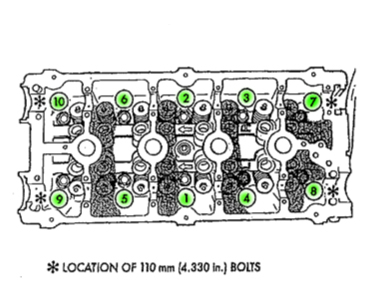
Note: The 4 short bolts are placed in the corners.
A. Torque all center bolts to 25 ft.lbs. (34 Nm), Torque the 4 corner bolts to 20 ft.lbs. (27 Nm) see Fig 1 for torque sequence.
B. Torque all center bolts to 50 ft.lbs. (68 Nm), Torque the 4 corner bolts to 35 ft.lbs. (47 Nm) see Fig 1 for torque sequence.
C. Re-torque all center bolts to 50 ft.lbs. (68 Nm), Re-torque
the 4 corner bolts to 35 ft.lbs. (47 Nm) see Fig 1 for torque sequence.
D. Tighten all bolts in the specified sequence (Fig 1) an additional 90° (1/4 turn).
Revised 2.4L Cylinder Head Re-torque Procedure
This information supersedes the previous technical bulletin, dated
March 25, 2005. The previous bulletin should be removed from your
files. This bulletin applies to vehicles equipped with a 2.4L engine
built between February 1, 2004 and April 5, 2005.
1. Using a six inch wobble plus extension friction ball and shallow
socket following the torque sequence (Fig. 1), loosen one bolt at a
time to 0 torque and then torque that same head bolt to 60 Ft-lbs.
2. Repeat step 4 for every head bolt one bolt at a time in sequence.
3. Verify that each head bolt is at 60 Ft-lbs before performing next steps.
4. After all head bolts have been verified to be torqued to 60
Ft-lbs , follow the torque sequence and turn the head bolts an
additional 90° (1/4 turn) (Fig. 1).
5. Following the appropriate procedures to install the cylinder head cover.
Some or all of the technical information was provided by the
Automotive Parts Remanufacturers Association (APRA). For more
information on technical bulletins available through APRA call
703-968-2772 or visit www.AutoBulletins.com.