Aluminum engine blocks have been around for many years for both stock and performance applications. Aluminum has a number of advantages over cast iron, the most obvious one being weight. An aftermarket aluminum V8 block will typically weigh about 80 to 100 lbs. less than a comparable factory cast iron block of similar displacement. Add a pair of aluminum cylinder heads, and you can probably get rid of another 30 to 40 lbs. of dead weight.
Aluminum has other advantages too. One is that it conducts heat much faster than cast iron (about three times faster). This means an aluminum block (or heads) can pull heat away from the combustion chamber when the engine is accelerating hard, reducing the risk of engine-damaging detonation. The superior cooling provided by an aluminum block and heads means you can often run a slightly higher static compression ratio for increased thermal efficiency and power, and/or advance ignition timing a few more degrees to start the air/fuel mixture burning a little earlier in the combustion cycle.
Aluminum is also relatively easy to weld compared to cast iron. If a block cracks, the crack can be ground out and filled in with a TIG welder. Welding can often save a block that would otherwise be destined for the scrap pile. If an iron block develops a crack in a cylinder, it can often be saved by sleeving, and cracks elsewhere in the block can sometimes be repaired by furnace welding. But it’s not as easy as TIG welding aluminum.
However, aluminum also has some disadvantages. Besides its higher cost, aluminum is softer than cast iron. This means the cylinders must either be sleeved with wet or dry liners, or plasma sprayed with some type of wear-resistant nickel-chromium coating such as Alusil or a similar material. Many late model Ford, GM, Chrysler and import blocks have cast-in-place iron sleeves, but some European makes have plasma sprayed cylinder coatings. As for aftermarket aluminum blocks, it’s mostly press fit cast iron, ductile iron or steel sleeves.
Machining Differences
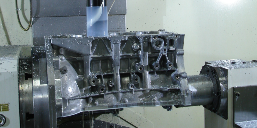
This brings us to the focus of this article, which is how machining aluminum blocks differs from machining cast iron blocks. Although you can buy finished, ready-to-assemble aluminum blocks from OEMs and aftermarket suppliers, many of you prefer to do your own finishing work. This includes sizing and finishing the main bores and cam bores, honing the cylinder sleeves (or bores if you are installing your own press-fit dry sleeves), and machining the deck surfaces.
Since aluminum is softer than cast iron, boring and milling bits last longer when machining aluminum. Carbide works well on both cast iron and aluminum, but if you are using superabrasives the best choice for aluminum is PCD.
The problem with CBN is that aluminum chips tend to stick to the tooling, which can increase the risk of smearing or streaking the deck surface when you are milling a block. One way to reduce the risk of this happening when machining aluminum with CBN is to lightly lubricate the surface of the metal with WD-40, olive oil or even furniture polish – or switch your tooling to PCD.
Different Alloys
Most cast aluminum engine blocks are made from one of three alloys: 319, A356 or A357. The 319 alloy is 85.8% to 91.5% aluminum, 5.5% to 6.5% silicon, 3% to 4% copper, 0.35% nickel, 0.25% titanium, 0.5% manganese, 1% iron, 1% zinc and 0.1% magnesium. The alloy is given a T5 heat treatment to harden and strengthen the metal before the block is machined to final dimensions.
For performance applications, the A356 and A357 alloys are most commonly used. These alloys have a higher percentage of aluminum (91.1% to 93.3%), more silicon (6.5% to 7.5%), a little more magnesium (0.25% to 0.45%) but less copper (0.2%), less iron (0.2%) and less zinc (0.1%). The alloy is relatively soft as cast, but ends up being much stronger after it receives a T6 heat treatment.
Billet aluminum engine blocks are made from a different 6061 “aerospace” alloy that is more ductile than A356 or A357, and is highly resistant to cracking under extreme pressure. The 6061 alloy in forged billet blocks is often pressure treated to decrease porosity and increase density. This gives 6061 billet a tensile strength of 60,000 to 70,000 psi, compared to 13,000 to 14,000 psi for A356 cast aluminum. That’s why the most demanding racing applications such as Top Fuel dragsters run 6061 billet aluminum blocks.
Internal Clearances
Although each of the common aluminum alloys have somewhat different physical properties, they all have a thermal coefficient of expansion that is more than twice that of cast iron. Consequently, when an aluminum block goes from room temperature to operating temperature, it will experience about twice as much growth in all directions as a cast iron block.
Changes in dimensions that result from heat can affect piston-to-cylinder clearances and bearing-to-bore clearances, though generally not enough to worry about according to the piston and bearing suppliers we interviewed – provided the engine does not overheat. Any engine that overheats runs the risk of scuffing pistons and galling valve stems.
How a block expands as it heats up depends on its design and the thickness of the metal in critical areas of the block. Because of this, some tolerances may change more or less than others depending on the block and the temperatures it is exposed to.
Most parts suppliers do not recommend different cylinder bore or main bore clearances for aluminum versus cast iron blocks. Steel backed aluminum and tri-metal bearings usually provide more than enough crush fit (.002 to .004˝) to prevent them from loosening up when the block gets hot. Even so, some engine builders will reduce main bore clearances slightly when they are building a performance motor for added insurance against the possibility of a spun bearing.
Line honing the mains is always recommended for all performance aluminum blocks. Many unfinished aftermarket blocks leave a few thousands in the mains so they can be honed. Use softer stones for aluminum. Some engine builders recommend honing mains that have steel caps with the engine block right-side-up and the caps on the bottom. Honing in this position will put the weight of the hone on the caps, equalizing the amount of material removed. Honing with the block upside down and the caps on top increases the risk that you will remove more aluminum from the block than steel from the caps.
The best advice for sizing the main bore in an aluminum block, according to one bearing supplier, is to aim for the smallest dimension that is listed in the range of acceptable tolerances. For example, the size range for the main bores in a 460 Ford is 3.1922˝ to 3.193˝. Following this advice, you would size the bores to the minimum dimension or 3.1922˝.
As for piston-to-cylinder clearances, the increased thermal expansion rate of aluminum is offset somewhat by the increased cooling it provides, so the overall change in clearance is usually not enough to affect anything – unless it’s an extreme application like Top Fuel where nothing lasts very long. The piston alloy (cast, hypereutectic or forged) will usually have much more of an effect on growth and changes in piston-to-cylinder clearances than the type of metal in the block.
If you’re worried about scuffing pistons, use an anti-friction coating on the piston skirts and/or open up the clearance slightly.
Changes in deck height will also occur more so in an aluminum block than a cast iron block. Although the change isn’t much, there might be a slight increase in deck height, which could increase piston-to-head clearance, reduce compression and loosen valve lash in a pushrod engine. Any of these changes can have an adverse effect on power if the change is great enough. However, most people we talked to on this subject said any changes that do occur are usually so small that they cause no noticeable issues.
If you are building an engine (aluminum or cast iron) with aluminum rods, however, thermal expansion can have a significant impact on piston-to-head clearances. Aluminum rods will grow in length much more than steel rods when they get hot. Most aluminum rod suppliers recommend a minimum piston-to-head clearance of .060˝ to accommodate thermal expansion. Some aluminum rods are also made .010˝ shorter for this reason.
Sleeves
Aluminum blocks can be machined to accept wet liners or dry sleeves, but dry sleeves are by far the most commonly used. Opinions differ as to how the deck surface should be machined to assure proper head gasket sealing. A lot of old school engine builders will leave the sleeves protruding from the block slightly to ensure gasket seal due to block growth. This may have been an issue with some aluminum blocks because of their design and alloy, but in many cases the problem of sleeves slipping below the deck surface is caused by sleeve placement rather than block growth.
A fairly common practice in seating sleeves is to pound them down with a 2×4 and a big hammer. Pounding the sleeves down into their bores is no guarantee a sleeve will not rebound back up and leave a gap below the sleeve. The best approach is to hone the block with the sleeves in place using a torque plate. This will help seat the sleeves in the block so they don’t move up or down. The block can then be decked and finished in the usual way for the type of head gaskets that will be used in the engine.
The recommended press fit for installing sleeves will vary somewhat from one block to another as well as the application.
To ensure proper fit and sleeve retention, here are some suggestions you can use:
1. After boring out original aluminum and iron, in preparation for sleeve installation, hone the block’s parent bore aluminum. This process ensures better interference pressed fit of the alloy and sleeve surface. Honing the aluminum will effectively plateau, or knock down, the microscopic peaks and valleys caused by the boring cutter tool. This allows a better mating surface with more efficient heat transfer from the sleeve to the aluminum. It also means you don’t have to use any Loctite or sleeve sealer if you hone the block’s parent bore aluminum. If you choose not to hone the bores before installing the sleeves, use Loctite or sleeve sealer to assist fitment and heat transfer.
2. The recommended average press fit is .0015˝. Minimum fit is .0005˝. Maximum interference fit is .002˝.
3. There is no interference press fit needed on the outside diameter of a flanged sleeve against the outer water jacket area.
4. For easier installation, heat the block from 200 to 275 degrees F. Place the sleeves in a freezer, or chill them with dry ice or liquid nitrogen. The sleeves will then fall into place with no resistance. If you are using liquid nitrogen to freeze the sleeves, heating the block is not needed.
5. Once all sleeves are installed, hold the sleeves down under a hydraulic press. Using a steel plate, or torque plate, with approximately a ton of pressure, hold the sleeves down while the block is cooling and crushing the sleeves into place. Once the block has cooled to room temperature, reheat it back up to approximately 180 degrees, and again rap the sleeves down with the hydraulic press. This should prevent the sleeves from slowly creeping up after installation.
6. It’s your choice whether to deck the top of the sleeves after installation. It is not critical, but it is recommended. Depending on your level of confidence, two options of decking can be used. Option #1 is to deck the aluminum prior to sleeve installation. Then, install sleeves allowing up to .002˝ of sleeve protrusion above gasket deck surface. This will provide a minor pinch for better gasket seal. Option #2 is to install the sleeves, and deck both the aluminum and sleeve tops all the way across the deck, with zero sleeve protrusion above the deck surface. Either method will work provided the sleeves have fully bottomed out on their seating surface.
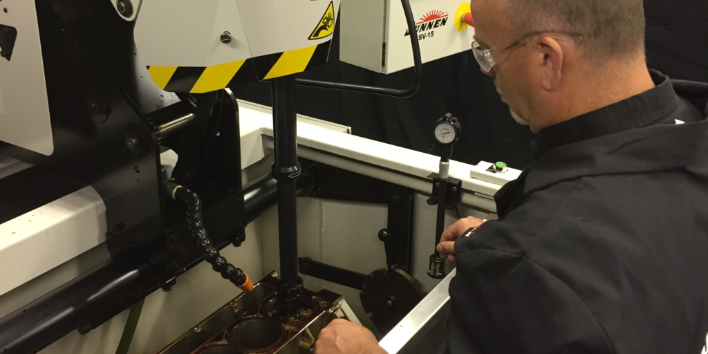
Honing Aluminum Blocks
Before you start the cylinder honing process in an aluminum block, you should get as much info as you can from your liner supplier regarding the liner material and its hardness. Why? Because the hardness of the liners affects the honing process and the pressure needed to achieve the desired finish.
If you are rebuilding an aluminum block and reusing the original sleeves (or the block has cast-in-place sleeves such as a Chevy LS or Ford modular V8), using a hardness tester to check the liners may help you achieve better results. Used sleeves are typically somewhat harder than virgin sleeves due to work hardening of the metal.
Low tension steel piston rings require very precise bore geometry to seal well. The rounder the bore the better. Checking bore concentricity and geometry is actually much harder than it looks. A simple bore gauge can tell you if the hole is close to specifications, but it can’t create a precise 3D map of bore geometry like a high dollar P.A.T instrument can. These are beyond the reach of most shops, but are used by OEMs and some honing equipment companies to check the accuracy of bore dimensions.
For most performance applications, you should be applying some type of plateau finish to the sleeves using a three or four step finishing process (a coarse hone to create the desired crosshatch for oil retention, followed by one or two finer stones to knock the peaks off the surface, followed by a brush to clean away any residual debris).
Crosshatch angle is critical because too much will cause the rings to spin too fast, while too little may not provide adequate lubrication for the rings. In most cases, a 30 to 45 degree inclusive angle works best in a performance motor. For stock street use, 45 degrees is usually recommended.