EFI systems require copious amounts of data to provide the EFI experience we expect. We use electrical sensors to relay engine operating conditions to the ECU, which are then used for its calculations. The ECU compares this data with user-defined tables along with calculations behind the scenes to manage the engine, transmission or any other sub-component correctly.
Sensors such as crank and cam can be 12v, 5v or magnetic pick-up, while others operate on a 0-5 volt reference or use a resistance relationship to ground such as a thermistor. EFI systems can employ numerous sensors to perform many tasks, including data acquisition, but this article will concentrate on only the required sensors. Understanding how each sensor in an EFI system functions can help us in diagnosis and tuning. Below are some common sensors and their uses.
Crank Sensor
The crank sensor, also referred to as crank position sensor, is the most important sensor in the EFI system. A crank sensor in its simplest form merely supplies the ECU with an rpm signal. If there is no rpm input, the ECU will not generate an output and the engine will not run.
Camshaft Position Sensor
A camshaft position sensor is not as critical as a crank sensor in that many applications will run without one unless it is required as an ECU input. Features such as timed sequential fueling, coil near plug “CNP” ignitions and individual cylinder timing all require a cam sensor input for correct function. This is because a complete cycle of a 4-stroke engine requires two complete revolutions of the crank making the crank input insufficient. Placing a sensor on the cam is the ideal location to identify a specific event such as the compression stroke of the No. 1 cylinder, thus meeting the requirement of a correct cam input.
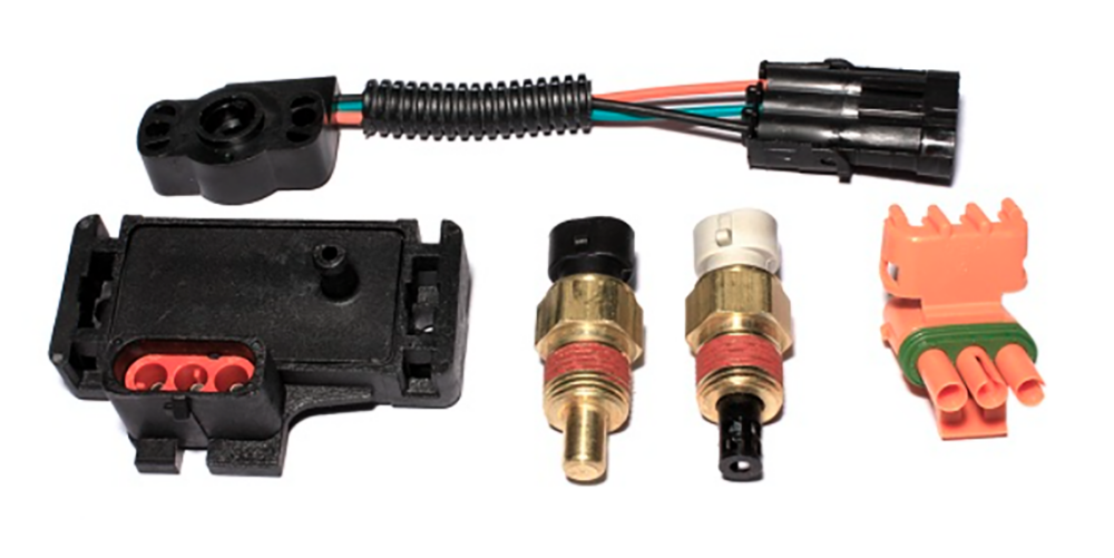
TPS or Throttle Position Sensor: 0-5V
A TPS is simply a potentiometer with a sliding wiper that outputs a voltage relative to the position of the throttle opening. Identifying the idle position is a critical function of the TPS since the ECU helps control idle by using timing trim and IAC position to meet the target idle speed. As the throttle is depressed and is no longer at idle, these features are turned off.
When the TPS is advanced past the idle position, the ECU activates the throttle follower control of the IAC. This opens the IAC to a specific opened position, which is programmed to close at a slower rate, bringing the engine down to idle after the throttle is closed.
The TPS is also used for accelerator enrichment (AE fueling), and typically, the faster the TPS is moved (rate of change), the greater the fuel flow to cover the throttle transition. TPS inputs are also used for the clear flood feature along with some transmission control parameters.
IAC, or Idle Air Control Valve
The IAC is an electronically controlled vacuum leak that is used to control engine rpm at the idle position. It is often referred to as a sensor, but in reality, it is an actuator since the IAC receives commands from the ECU.
The primary function is to increase or restrict the air leak into the engine in order to achieve the target idle speed. Another function is to provide additional air to the engine while cranking to emulate opening the throttle for a quick start. The rpm flare encountered after a start is the function of how open the IAC is during cranking. Most of the IAC variables are based on the coolant temp sensor with input from the TPS also.
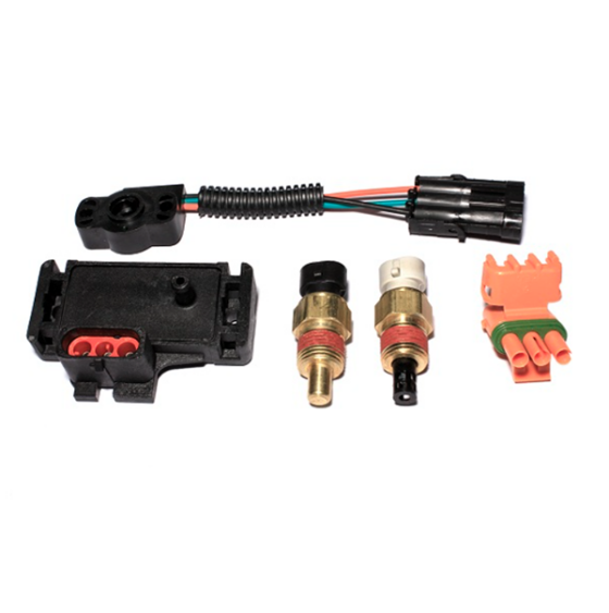
CTS or Coolant Temperature Sensor: Thermistor
As a thermistor, the resistance valve relative to ground allows the ECU to calculate coolant temperature. The primary function is to provide fuel correction depending on coolant temp especially when cold. Although similar to a carburetor choke that increases fueling while cold, an EFI system will just add the additional fuel, no choke required. Along with modifying fuel percentages, we can also offset the timing and other variables that are coolant dependent.
IAT or Inlet Air Temperature Sensor: Thermistor
Another sensor of the thermistor family, the IAT is used to measure inlet air temps. This sensor is more important than many think, but in a subtle way. When tuning in Speed Density, the ECU uses air temp to help calculate an air density figure in order to help provide greater accuracy of fueling during closed loop compensation. Also, the IAT is used heavily in boosted applications, providing spark and fueling modifiers for tune-up corrections based on inlet air temperatures.
MAP or Manifold Absolute Pressure: 0-5V
The MAP sensor for all intents and purposes is nothing more than an electrically controlled vacuum gauge and is required when tuning in the Speed Density algorithm. Much like a regular vacuum gauge, it measures the differential pressure in the intake over atmosphere. High-pressure readings in the intake indicate greater load as the engine moves towards equilibrium with outside pressure at wide open throttle.
Conversely, lower pressure readings indicate a “vacuum” associated with deceleration. The ECU uses these pressure values to identify engine load and then delivers the programmed primary fuel and timing for the respected load. MAP sensors are rated in bar with a 1 bar MAP sensor equal to 1 atmosphere or 14.7 psi. In order to read boost, a minimum of a 2 bar MAP is required with a maximum boost pressure reading of 14.7 psi. A 3 bar has a 29.4 psi boost range and so on. Speed Density is the tuning algorithm employed by most aftermarket ECUs due to its flexibility.
MAF or Mass Air Flow: 0-5V
A Mass Air Flow meter measures the actual air volume used by the engine and is typically relegated to OEM applications. Since MAF measures the actual air used, tuning for a target air/fuel ratio is more precise and is considered superior to the Speed Density (MAP sensor) algorithm. Where MAF is at a disadvantage is when the incoming air is no longer laminar over the sensor creating erroneous readings to the ECU.
These disruptions in air flow can be the result of an aggressive camshaft, moving the sensor from the OEM location or rerouting inlet piping making Speed Density the best option for non-stock applications. Boosted applications can also cause the MAF to fall out of its specified range causing a lack of accurate data. In some cases, OEM management systems will incorporate speed density along with MAF taking advantage of each to provide the best fuel control.
As you can see, most EFI sensors are relatively basic and provide the same data we have used in automotive diagnosis for years. But, knowing the job of each sensor and how it applies to the ECU can help with diagnosis and fine tuning your EFI system.
Andrew Starr, Starr Performance and Consulting – Starrperformancetuning.com