The relationship between connecting rod length, piston compression height and compression ratio is often misunderstood, largely due to the misuse of the term “compression”. In all honesty it probably shouldn’t be applied to piston terminology at all except as it relates to the shape of the piston crown surface. Compression is a volume related term that refers to compression ratio. It bears no relationship the mechanical link created by a specific crankshaft stroke and connecting rod center-to-center length or the pin position that brings the piston crown essentially even with the top of the bore.
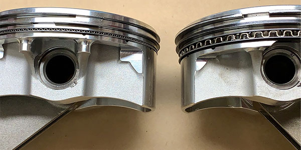
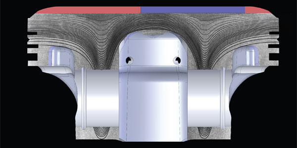
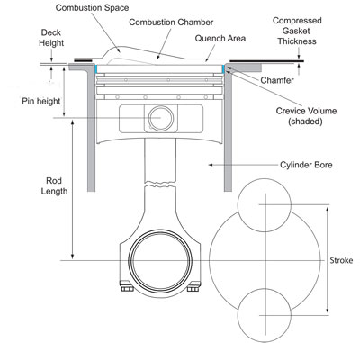
Compression Height (compression distance) is the dimension from the flat top of the piston crown (not inclusive of dome or dish) to the centerline of the piston pin.
This should always be referred to as the pin height to avoid confusion.
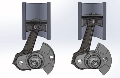
We often say an engine has some specified compression ratio, such as 10:1 compression for example. But it is not an appropriate usage when referring to the mechanical interaction of crank stroke and rod length. Pin height is the preferred term and you can see the relationship in the accompanying illustration. With a fixed stroke length, changing the rod length affects two things, neither of which is the compression ratio. It dictates the required pin height to bring the piston crown flush with the block deck at TDC. It also influences the approach and departure speed of the piston relative to TDC and to some degree the piston’s dwell time at TDC.
Key Engine Dimensions
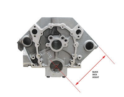
- Block deck height
- Stroke length
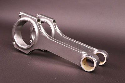
- Rod center to center length
- Pin height
The crank throw, connecting rod and piston must all fit within the block height dimension so that the piston deck comes nearly flush with the deck surface at TDC. Because the crank throw rotates about its own center at the main bearing you can see that only half the stroke length is used when the piston is at TDC. The rest of the distance is taken up by the rod length and the pin height of the piston. So, the reciprocating assembly final dimension is calculated as:
½ stroke length + rod length + pin height
Since block height is fixed within a narrow window available for deck milling, the combination of stroke length, rod length and pin height must add up to the same height with a small tolerance for desired deck height and piston to head clearance which also incorporates gasket thickness. A common practice in performance circles is to zero-deck the block. That means that the combination of one half the stroke length plus rod length and pin height equals the fixed deck height of the block. The flat portion of the piston top is exactly even with the deck surface of the block. This forces the builder to select the appropriate compressed gasket thickness to control piston to head clearance. Not surprisingly, most performance head gaskets are .039″ – to .042″ thick when compressed. The commonly accepted minimum piston to head clearance with steel connecting rods is .035″.
The stroke length is almost always chosen first as it relates to the bore and stroke combination for the desired displacement. Rod length is usually specified next based on the application. Theory on this is widely debated and often contradicting, but as a rule, shorter rods are usually chosen to gain a more rapid departure from TDC as the piston starts down the bore. This opens a larger cylinder filling space more quickly so that a high velocity intake system can start filling the cylinder faster. It is often used to enhance throttle response on applications that are frequently throttled.
Pistons with shorter rods arrive at TDC more briskly and don’t hang around long before they depart swiftly. The piston achieves maximum velocity sooner and at less crank angle, which reduces cylinder volume exposure at the point of maximum pressure differential. Appropriate intake valve timing is required to ensure optimum efficiency under these conditions. Since the piston achieves maximum velocity sooner, the intake valve can be opened sooner to take advantage of the cylinder pressure differential. Less overall cylinder volume is exposed at this point, but the early initiation of flow will chase the piston down the bore as volume exposure rapidly increases. This is commonly referred to as the piston tugging harder on the charge due to its increased acceleration.
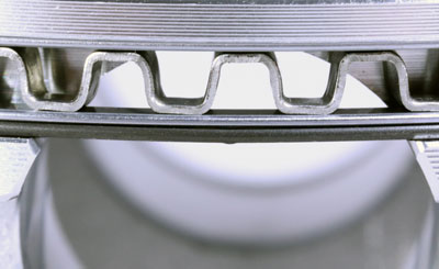
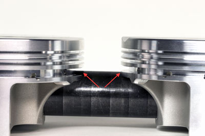
Many racing engines use longer connecting rods to help reduce piston weight while having positive effects on torque curve shape and positioning and combustion efficiency. Longer rods typically require shorter, lighter pistons. This pushes the ring pack higher on the piston. In normally aspirated applications, builders appreciate this because they like to move the ring pack up to lighten the reciprocating assembly, improve piston stability and minimize unburned gasses in the crevice volume above the top ring. However, longer rods in a supercharged application can be problematic because boosted applications need to move the ring pack down the piston to move it farther from excessive heat. Longer rods make this difficult to accomplish as the pin bore intersects the oil ring groove. In many cases a shorter rod can be specified for boosted applications because boost pressure reduces the need for the critical rod/stroke tuning relationships required for efficient normally aspirated operation.
In effect, connecting rods provide an additional tuning component in a competition engine. As rod length (center to center) varies, it affects piston motion such that it can be used as a tuning tool. By influencing piston acceleration and velocity it dictates the rate at which a differential is created between atmospheric pressure (above the carburetor) and cylinder pressure during the intake stroke. Accordingly, it impacts major contributors to the VE equation, i.e. intake and exhaust path cross sections, valve event timing and optimum ignition point.
Faster exposure to atmospheric pressure improves cylinder filling and thus VE provided intake tract dimensions and valve event timing are appropriately sized and synchronized. It is important to recognize that piston acceleration and velocity are both zero at TDC and BDC. At all points in between, acceleration and velocity are dictated by rod length. For any given rod length, the piston achieves maximum velocity at a precise point in the stroke relative to the crank angle where the rod axis is 90° to the crank throw (typically about 70-75° of crank angle). This point represents the highest rate of pressure drop exposure in the cylinder and is closely tied to intake valve timing for optimum cylinder filling.
Once rod length is chosen, you have two parts of the equation. Since the rod length and stroke are now fixed, the pin height is the remaining variable. To find the necessary pin height, add the rod length and half of the stroke and subtract the result from the block deck height. Blocks that have not been decked typically provide a fudge factor of about .020″. This is often removed when the block is zero decked to match the piston crown. At this point, the builder can evaluate the available room for the ring pack and determine whether a longer rod negatively impacts ring location.
Note that none of this affects compression ratio. The piston crown still stops at the block deck surface, thus the combustion space (volume) above it remains unaffected unless you alter the head gasket thick- ness. The compression ratio can only be altered by increasing or decreasing the volume of the combustion space above the piston at TDC. And, because the relationships are mechanically fixed, dynamic compression ratio can only be affected by cam timing.
You can use an online calculator (such as that at www.diamondracing.net) to juggle all these figures and determine the best combination for your application. When ordering pistons, your tech rep can also assist you in homing in on the best combination. The tech can also help you with ring pack placement to avoid issues with the valve reliefs. There are multiple ways to package these components depending on the requirements of your application and the tech guys will keep you within the necessary limits to protect your investment.
This article was sponsored by Diamond Pistons. For more information, please visit our website at www.diamondracing.net