
Engine building is all about attending to the details. The professionals know that all is not as it seems when it comes to something as simple as valve lift. We had an opportunity to discuss this with Ben Strader, president of EFI University, where he and his staff not only teach engine building and EFI tuning, but also apply what they learn on the dyno. Amid a day-long discussion concerning engine building, Strader mentioned that one of the best ways to evaluate the quality of a valvetrain is to rate it based on stiffness.
Valvetrains are subject to essentially two different ways load is applied, generally referred to as static and dynamic. Static load is simply the load you can measure with a spring load tester and then multiplied by the rocker ratio. For example, if we have 500 pounds of spring load at maximum valve lift and a rocker ratio of 1.5:1, the rocker arm, rocker stud, pushrod, and lifter are exposed to a static load of 750 pounds (500 x 1.5 = 750 lbs) of force.
The second type is called dynamic load which accounts for the forces applied to the valvetrain while accelerating and decelerating the valve at various engine speeds. These dynamic forces are incredibly high and impart loads much greater than what we can measure statically since these components are accelerating at incredible speeds even at engine speeds of 6,000 to 7,000 rpm. Of course, the load increases with each jump in engine speed.
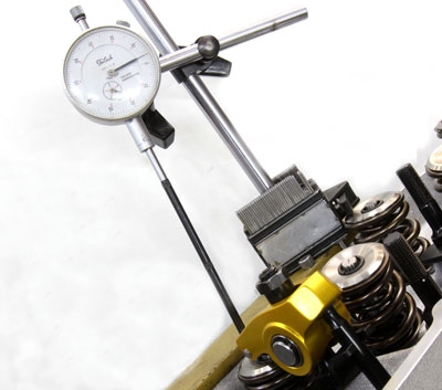
One way we can verify or measure the effective stiffness of the valvetrain is to perform a stiffness test. The usefulness of this test is in its simplicity. The process involves comparing maximum valve lift with a checking spring against the lift created using the actual valve spring. The average enthusiasts might consider this to be a waste of effort because the numbers should be the same. But all it takes is a simple test like this on a performance engine to realize that there’s some bending happening in the valvetrain.
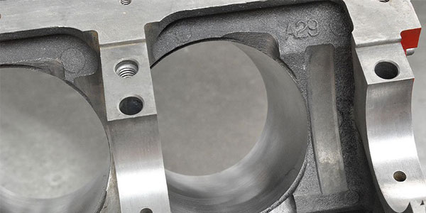
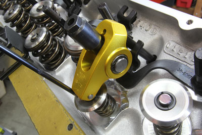
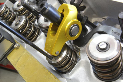
Let’s use a real-world example to show how this works. We started with a big-block Chevy by measuring maximum valve lift on the exhaust side by using a checking spring instead of the actual valve spring.
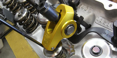
The test used a Crane 1.7:1 aluminum roller rocker, an 0.080-inch wall thickness, 3/8-inch diameter Trend pushrod, and a mechanical roller lifter. Using the checking spring, we measured maximum lift on the exhaust side at 0.746-inch. We then switched to a cylinder already loaded with the intended valve spring at its proper installed height. This spring checked on our Longacre load tester with 235 pounds on the seat.
We then repeated the lift test except with the dual spring in place which revealed a peak lift of 0.710-inch. We ran through this test three times to ensure this number was correct. This meant that by adding spring pressure, this typical big-block rocker stud combination had managed to lose 0.036-inch of valve lift. Strader offered a list of potential sources where this bending could originate that we’ve included.
Our first thought was to test for pushrod deflection. We measured the valve spring load at 0.710-inch of valve lift and came up with 610 pounds. We will assume a 1.7:1 rocker ratio. We can also assume the actual ratio changes based on the position of the rocker over the valve at max lift. The rocker ratio multiplies the load that the pushrod sees – which means the load on the pushrod is 610 x 1.7 = 1,037 pounds. This is the static load and does not take into account the acceleration rates imposed on the system that could easily achieve g-loads of 250 to 300 g’s. But that’s a story for another time.
While it’s likely that the pushrod will deflect slightly with this much load because it is not perfectly vertical, this may not the only source of deflection. Because this is a stud-mounted rocker arm system, it’s entirely possible that even with high quality 7/16-inch rocker studs that they could also deflect. This is where a stud girdle would be of further benefit. The ideal solution would be the addition of a quality shaft rocker system such as one from Jesel or T&D but by this time, unless your combination calls for spring loads that approach 1,000 pounds open, the return on the investment might not be strong enough.
The rocker arm is another place where the system could be deflecting. Aluminum is the most often-used material for rockers in an effort to reduce weight, but this comes at a price. While lighter, aluminum is far less rigid when compared to steel. However, in this case, we tested both aluminum and steel versions and recorded no difference in maximum lift. Of much greater concern is the effect of pushrod length on the entire lift curve. We did not perform a refined pushrod length test on this engine to determine the ideal length. If pushrod length is not ideal, this will affect the overall rocker ratio by changing the distance the rocker travels across the tip of the valve. This might be cause for a separate story on the effect of pushrod length on lift.
All of this effort to reduce deflection focuses mainly on improving the overall stiffness of the valvetrain. Strader says that he learned a simple way to calculate the stiffness that can then be used to evaluate different valvetrains from a noted cam designer. His source recommended simply dividing the peak valve spring load by the amount of the deflection. In our case, this was a spring load of 610 pounds divided by the deflection of 0.036-inch. This generates a stiffness rating of 16,944 pounds-per-inch. Note this is a load rating, not a pressure rating so the load is expressed in pounds-per-inch.
Strader’s source also created a rating system based on this load number and considers 20,000 pounds/inch and above to be acceptable. If your system generates a rating of 25,000 pounds/inch or more –consider your efforts justly rewarded.
As you can see, this big-block is fairly close to that 20,000 lbs/in threshold stiffness number. The variables are both the spring load and the amount of deflection. Achieving a higher number could be attained by either reducing the spring load – which most engine builders don’t prefer – or to increase the stiffness by reducing the deflection. All this information also only relates to static testing and only the relative stiffness has an impact on the dynamic part of this equation. In reference to that, reducing the weight with a tool steel or titanium retainer, for example, is one place where this has little impact on stiffness yet would drastically reduce the dynamic load the spring is forced to deal with at high rpm.
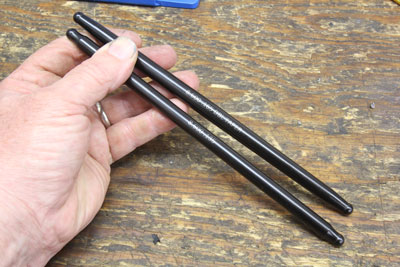
This brings us back to our original test. We decided this engine’s low-hanging fruit might be the 3/8-inch, 0.080-inch wall thickness pushrods. So we ordered a set of Trend pushrods in the same 3/8-inch diameter and length but with a thicker, 0.135-inch wall that is rated to be 37 percent stiffer.
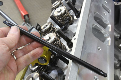
Plugging the thicker-wall pushrod into our 540ci test engine immediately improved the valve lift under actual spring load from 0.710 to 0.718-inch. That’s an instant valve lift improvement of 0.008-inch. We were hoping for more, but considering the ease with which this gain was achieved, it’s hard to argue the improvement. This also required recalculating the stiffness rating. There was only a slight change in the spring load, with the 0.718-inch lift working against 619 pounds. Calculating the rating then produced a stiffness rating of 22,107 lbs/in which is a significant improvement over the original 16,944 lbs/in number. Doing the math, that’s a 30 percent improvement in valvetrain stiffness just by changing to a slightly thicker wall pushrod! That’s the most amazing part of what would appear to be an otherwise minor change in deflection.
To take this evaluation one step further, we tested a 7/16- to 3/8-inch fully tapered pushrod in that same exhaust location using the same length pushrod. Running through the lift curve once more, we saw only a very slight improvement of 0.002-inch of valve lift over the 0.135-inch wall thickness pushrod. So in this case, there was little to be gained. In a system with a maximum spring load of over 800 lbs/in, this is where the larger tapered pushrod would see more improvement.
There’s much more to this story but there’s enough here to keep you busy checking valvetrain deflection on your own engine. We’d like to thank Ben Strader and EFI University for his willingness to share this information. This is just one small part of what his company offers in its Competition Engine Development (CED) course, so if this little snippet of information intrigues you, there’s much more to learn. You can find details on the CED course at efi101.com.
Sources of Valvetrain Deflection
- Rocker Stud Deflection
- Pushrod Deflection
- Rocker arm Deflection
- Rocker Travel Across Valve Tip
- Length of Pushrod
- Lifter Bore Clearance
- Pushrod Angle
- Cam Core Diameter
This article was sponsored by Trend Performance. For more information, please visit our website at www.trendperform.com