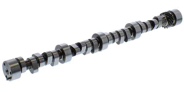
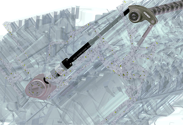
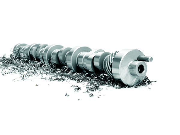
While I certainly understand what people mean when they say that a “camshaft was worth 40 hp!” I believe the strongest and most fundamental difference in approach to custom camshaft theories begins with your perspective. For years, I believe our industry was tied up thinking about camshafts solely based on the picture below:
I love that image. I have seen it countless times in memes, and worked closely with Trent Goodwin at COMP to create it to show customers the output of our designs. However, a good design should never start at the lobe surface. When we look at all the components between the camshaft and the valve in this image, it is very apparent that they are all tied together, but where should we start?
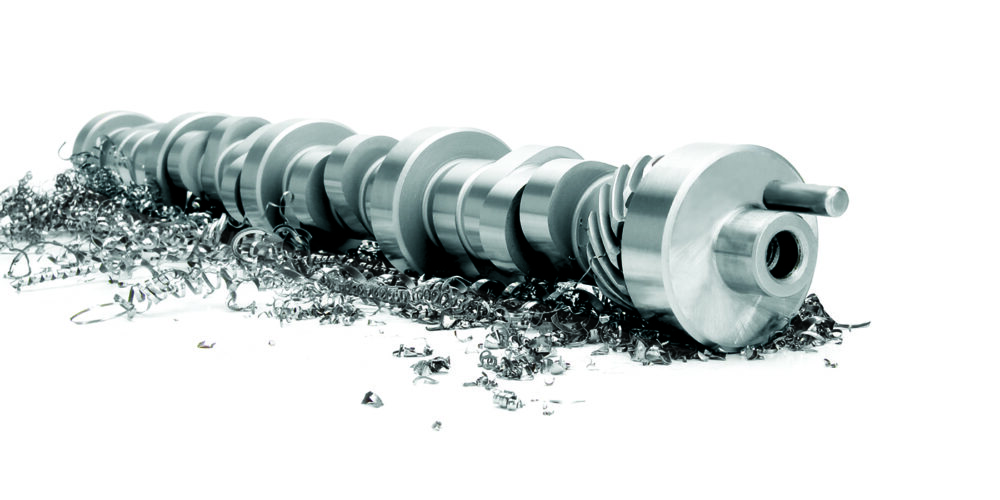
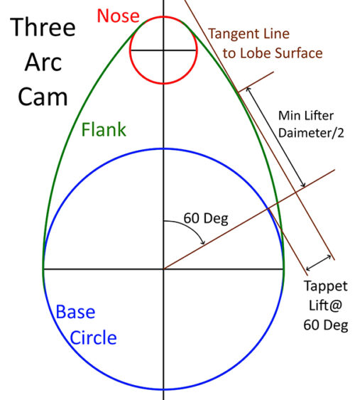
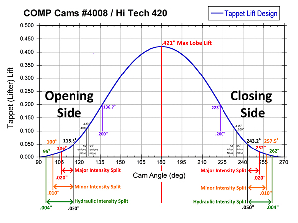
If you go back to the 1900s to 1940s, the common place to start WAS the camshaft lobe. Engineers and engine designers drew one circle for the base circle, one for the nose, and then connected the two with arcs in-between (as seen in the Three Arc Cam photo). Eventually that was improved by shifting their focus to the lifter or tappet rise from the base circle. Harvey Crane is probably the most-talented person ever at designing the most beautiful lift curves for tappet motion, with amazing precision controlling the tappet lift, velocity, acceleration, and jerk every half degree, and ensuring that every transition was smooth between sections.
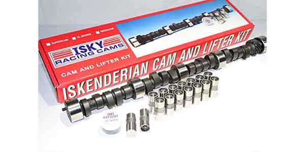
However, as great as Harvey was, I believe Ed Iskenderian and others had one area where they were even better than Harvey. From Ed onward, there has always been a group focused on valve events, not the camshaft. You see this clearly in the motorcycle world where everyone speaks about the four valve events (Exhaust Valve Opening or EVO, Intake Valve Opening or IVO, Exhaust Valve Closing or EVC, and Intake Valve Closing or IVC). In the OHV automotive camshaft world, instead of those events, most speak of lobe separation, advance, and intake and exhaust durations.
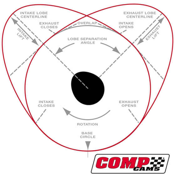
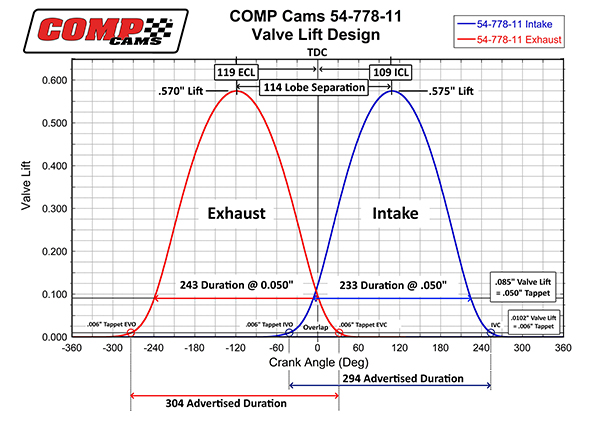
Mathematically, both the valve events and the LSA and duration system give you the same result, but your focus matters. People who focus on lobe separation are always looking at the top of the chart below (54-778-11), but the engine is responding primarily to the valve events (circled), then secondarily, to how quickly the valve moves from those events up the flanks into the heart of the region where the cylinder head maximizes air flow. If you focus on the top, you start to believe there is something “magic” about lobe separation, like “a tight 105 LSA camshaft is super snappy” or “a wide 119 LSA camshaft will not accelerate.”
The funny part of that is a modern NHRA Pro Stock or Pro Mod car will go through five gears to above 10,000 rpm in well under 7 seconds. They accelerate faster than anything I deal with and have wider LSA values to optimize their valve events while keeping the valves from “merging” with those pesky pistons that drive the cars down the track.
Besides taking our eyes off the ball of what matters, the focus on the camshaft or lifter motion causes two other major issues. First, it totally ignores the importance of rocker ratio on valve durations. Second, it ignores the duration loss and acceleration limits that are due to system stiffness.
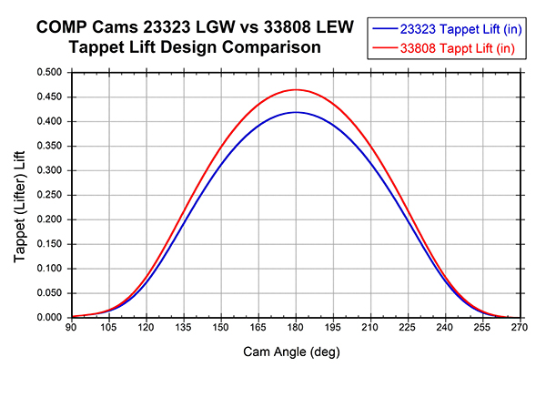
Let’s look at the tappet vs valve specs first. In the figure on the next page, we see the 23323 design in blue that is 287 duration at 0.020”, 256 duration at 0.050”, 178 duration at 0.200” and has .419” lobe lift. This is COMP’s modern Low Shock LGW series, which I designed for my own road race engine. This is a great profile, but looks like a soft “pooch” compared to the faster 33808 series in COMP’s LEW series in red. This is one of the newest series used in circle track applications with 291 duration at 0.020”, 261 at 0.050”, and 187 at 0.200” tappet lift. Anyone could look at these tappet lift specs and tell you that the LEW with 9 degrees more duration at 0.200” would walk all over my baby 23323 design.
The focus on the camshaft or lifter motion causes two other major issues. First, it totally ignores the importance of rocker ratio on valve durations. Second, it ignores the duration loss and acceleration limits that are due to system stiffness.
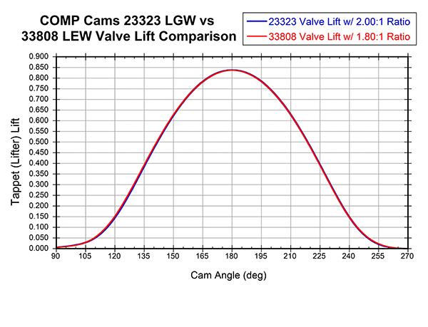
However, look what happens when the 23323 LGW is run with a 2.0:1 rocker vs the 33808 LEW design with a common 1.8:1 rocker. The newer LEW is still a little faster opening, but for the most part the differences simply disappear (seen on page 20)!
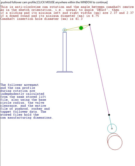
The tappet velocity, tappet acceleration, tappet lift and tappet durations are all much lower on the LGW, but the engine does not know or care about what the “tappet” sees. It only knows what the valve DOES. If we started by looking at the valve, we would have seen that immediately as these designs are extremely similar from the valve design point of view. When using the 4stHEAD design package, I can start with a “Static Valve Motion” or SVL design and then run that through a conversion to the resulting tappet motion and cam surface. Sometimes (often with earlier engines), I will not be able to grind the camshaft required to achieve that static valve lift, so we tweak the valve motion design until we get something that cam be made and is as close to the desired valve motion as possible (or practical).
All this talk about “static” valve motion brings us to the final point, and that is the engine does not respond to how the valve moves when you turn everything over by hand with a flow bench spring. It reponds to the “dynamic” valve motion at speed. This is where camshaft or valve motion design becomes extrememly fun!
Everything in the system is flexing, robing you of duration and performance. However, adding mass to reduce deflection required increased spring force to keep it under control, and every part is also vibrating. To add insult to injury, the valve springs’ own mass (which increases with load for a given stress limit) is probably the worst enemy to overall valvetrain control.
With all this going on, what is an engine builder to do to stay in front of the curve with respect to valvetrain? Let’s break it down into a few solid takeaways:
1) Always start at the valve
There is a reason why many sanctioning bodies put a minumum limit on valve weight. Ligther valves are easier to move quickly and require less load and stiffness to control.
2) Focus on air flow
A good camshaft can do wonders with a great cylinder head, but even the best camshaft cannot do much with a lousy cylinder head. You even need less time to move air through a better “door” into the combustion chanber, so less duration as flow improves.
3) Think about valve events not LSA
Sure, we have to grind those new lobe designs at some angles relitive to the dowel pin or key on the camshaft, but focus on what primarilty matters – those events!
4) Treat the entire valvetrain as a system
Often I will start thinking about the valve spring and port flow when selecting a camshaft. From there I will look closely a the rocker ratio and system stiffness to evaluate how much acceleration we might be able to control at the required engine speed. The camshaft is the last part I consider in “cam design.”
5) Have your valvetrain evaluated on a spintron
It is difficult to have this done, but EFI University has brought some of the top-level technology developed both at COMP Cams and with several NASCAR and Pro Stock teams and made that avalible to sportsman racers. This is not for everyone, but like windtunnel testing, is something that might be more afoordable and useful than many would expect.
6) Work with someone you trust on the entire system
One of the things I was most proud of during my time at COMP was we would help customers even when we did not have all the parts. We wanted racers to run Jesel or T&D rockers where allowed and knew the valve springs offered by PSI and JHE almost as well as our own. You want to work with someone who sees everything as a “package!”
7) Remember that we still have to grind a camshaft…
All this talk about valve motion and a systems appoach is awesome, but at the end of the day you have to take a design and find someone you trust to grind it accurately and in a timely manner. That cam may not directly “make 40 hp,” but you will lose a lot more than 40 hp without a good camshaft, unless you have some other means to control the valve.
8) If you want to learn more consider my book.
Two or three years ago, I started writing a book for CarTech. The illustrations and topics are covered far better in the 191 pages of High-Performance Cams & Valvetrains: Theory, Technology, and Selection than I could hope in this short article. However, I hope this shorter look is helpful as you dig into improvents to your valvetrian system. EB